
FinFET vs MOSFET Operation
Interactive Audio Lesson
Listen to a student-teacher conversation explaining the topic in a relatable way.
Introduction to Device Structures
🔒 Unlock Audio Lesson
Sign up and enroll to listen to this audio lesson

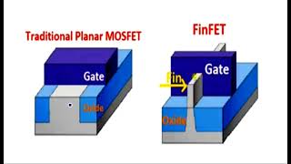
Today, we'll start by understanding the structural differences between FinFETs and MOSFETs. What can you tell me about their channel geometry?

Well, MOSFETs have a flat channel, while FinFETs have a vertical fin structure.
Exactly! The vertical fin in FinFETs helps improve gate control. Can anyone think about why that might be advantageous?

I think it allows the gate to control the channel more effectively because it surrounds more of it.
That's right! By wrapping around the fin, the gate achieves better electrostatics. Remember, we can call this ‘wrap-around gate control’! Now, what do you think this means for leakage currents?

I guess it would reduce leakage current since the gate controls the channel more closely.
Great observation! Let's move on and discuss the impact of these structural differences on the I_on/I_off ratio.
Impact on Electrical Characteristics
🔒 Unlock Audio Lesson
Sign up and enroll to listen to this audio lesson

Now that we've covered the structures, let's delve into performance metrics. Can anyone explain the significance of the I_on/I_off ratio for these devices?

A higher I_on/I_off means more efficient switching? Right?
Correct! FinFETs typically have a higher I_on/I_off ratio compared to MOSFETs. This is due to better control over short-channel effects. What are short-channel effects?
They are issues that occur in smaller devices, making it hard to turn the transistor off completely.
Exactly! With FinFETs exhibiting excellent short-channel effect tolerance, they are suitable for modern scalability. Who can tell me about subthreshold swing now?
Subthreshold swing is the rate at which current changes as we change the gate voltage below the threshold voltage.
Fantastic! FinFETs achieve a swing of less than 70 mV/decade, significantly better than MOSFETs. Why is a lower value better?
It means we need less voltage to control the current, which is better for energy efficiency!
Spot on! Energy efficiency is critical for modern applications! Let's summarize what we learned today.
Scalability and Future Use
🔒 Unlock Audio Lesson
Sign up and enroll to listen to this audio lesson
Finally, let’s explore scalability. Why are FinFETs considered more scalable than traditional MOSFETs?
Because they can maintain performance even as transistors get smaller.
Exactly! Their structure allows them to handle smaller dimensions better, which is essential for the industry's move to nodes below 10 nm. What implications does this have?
It means we can keep packing more transistors in the same area without losing performance!
Correct! Their enhanced performance metrics make them the preferred choice for advanced semiconductor manufacturers. Can anyone recall a major manufacturer that uses FinFET technology?
Intel and TSMC both use FinFETs in their latest chips.
Great recall! In summary, FinFETs outperform MOSFETs in several key areas, making them a standard for advanced technology nodes.
Introduction & Overview
Read summaries of the section's main ideas at different levels of detail.
Quick Overview
Standard
FinFETs significantly enhance device performance through improved gate control and reduced leakage compared to planar MOSFETs. Key differences include channel geometry, scalability, and subthreshold swing, impacting their application in modern technology.
Detailed
FinFET vs MOSFET Operation
This section provides a detailed examination of the operational differences between FinFETs and traditional planar MOSFETs, focusing on critical features that affect overall device performance. FinFETs, with their vertical fin geometry, allow for improved electrostatic control over the channel due to the gate wrapping around multiple sides. This results in:
- Significantly Better Short-Channel Effects (SCE) Tolerance: FinFETs demonstrate excellent control over short-channel effects compared to MOSFETs.
- Higher On/Off Current Ratio (I_on/I_off): The vertical structure and multi-gate configuration yield a considerably higher I_on/I_off ratio, leading to energy-efficient operation.
- Reduced Subthreshold Swing: FinFETs achieve a subthreshold swing of less than 70 mV/decade, while MOSFETs typically exceed this value.
- Improved Scalability: FinFETs are better suited for scaling down to smaller technology nodes, making them ideal for modern semiconductor manufacturing, unlike their planar counterparts.
In summary, while both devices serve similar functions in integrated circuits, FinFETs offer enhanced characteristics necessary for sub-10 nm technology nodes, thereby being the preferred choice for advanced semiconductor applications.
Youtube Videos


Audio Book
Dive deep into the subject with an immersive audiobook experience.
Channel Geometry
Chapter 1 of 6
🔒 Unlock Audio Chapter
Sign up and enroll to access the full audio experience
Chapter Content
Feature
Planar MOSFET
FinFET
Channel Geometry
Flat
Vertical fin
Detailed Explanation
In traditional planar MOSFETs, the channel where the current flows is flat and two-dimensional. This design creates limitations in terms of electrostatic control and performance, especially as transistors become smaller. Conversely, FinFETs utilize a vertical fin structure, which allows for three-dimensional control over the channel. This design inherently provides better performance and efficiency by increasing the gate’s surface area exposure to the channel.
Examples & Analogies
Think of the difference between a flat pancake (planar MOSFET) and a tall cake with multiple layers (FinFET). A flat pancake has limited surface area to absorb syrup (the gate control), while the layered cake provides much more surface area, allowing for better syrup absorption and distribution.
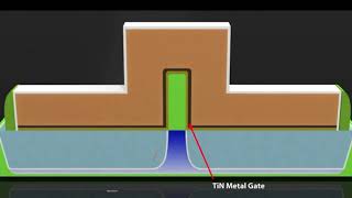
Gate Control
Chapter 2 of 6
🔒 Unlock Audio Chapter
Sign up and enroll to access the full audio experience
Chapter Content
Gate Control
Single side
Three sides
Detailed Explanation
Gate control refers to how effectively the transistor can control the channel through which current flows. In planar MOSFETs, the gate typically controls the channel from a single side. This can lead to issues such as unwanted leakage current. In contrast, FinFETs have gates that wrap around the channel on three sides, offering significantly enhanced control over the channel and allowing for a more precise management of the current. This results in better efficiency and lower power consumption.
Examples & Analogies
Imagine trying to control a water flow from a single faucet handle (single-side gate control on MOSFET) versus three handles on a multi-way valve (three-side gate control on FinFET). The multi-way valve allows for finer adjustments and greater control over the amount of water flowing through, much like how FinFETs provide enhanced gate control.
Short Channel Effects (SCE) Tolerance
Chapter 3 of 6
🔒 Unlock Audio Chapter
Sign up and enroll to access the full audio experience
Chapter Content
SCE Tolerance
Poor
Excellent
Detailed Explanation
Short Channel Effects (SCE) refer to performance issues that occur as transistors decrease in size. Planar MOSFETs suffer from significant SCE due to their geometric limitations, often leading to reduced performance and reliability. FinFETs, however, are designed to tolerate SCE better because of their 3D structure, which allows for improved electrostatic control over the channel, even as sizes shrink. This makes them more reliable in modern, small-scale applications.
Examples & Analogies
Consider a small garden where you have a limited amount of water for your plants (short channel effects). If the garden is flat (planar MOSFET), some plants might not get enough water due to uneven distribution. With a vertical garden (FinFET), you can ensure all plants receive adequate water thanks to better channel control.
On/Off Current Ratio
Chapter 4 of 6
🔒 Unlock Audio Chapter
Sign up and enroll to access the full audio experience
Chapter Content
I_on/I_off Ratio
Moderate
High
Detailed Explanation
The on/off current ratio is a measure of how well a transistor can switch between conducting (on) and non-conducting (off) states. Planar MOSFETs generally have a moderate ratio, which can lead to unwanted leakage when in the off state. FinFETs deliver a high I_on/I_off ratio, indicating they are much better at switching off completely and maintaining low leakage currents when not in use. This characteristic is vital for energy efficiency in modern electronics.
Examples & Analogies
Imagine a light switch. A traditional switch (planar MOSFET) flickers at times when you think it’s off, allowing some light (leakage). A high-quality switch (FinFET), however, completely cuts off the light when off, ensuring no light leaks through.
Subthreshold Swing
Chapter 5 of 6
🔒 Unlock Audio Chapter
Sign up and enroll to access the full audio experience
Chapter Content
Subthreshold Swing
70 mV/dec
<70 mV/dec
Detailed Explanation
Subthreshold swing indicates how effectively a transistor can transition from off to on state in response to voltage changes. For planar MOSFETs, this value is typically greater than 70 mV/decade, which implies poorer control over this transition. On the other hand, FinFETs achieve subthreshold swings of less than 70 mV/decade, meaning they can respond to voltage changes more sensitively and efficiently, which is crucial for fast-switching applications and power savings.
Examples & Analogies
If you think of a car's accelerator pedal, a planar MOSFET feels like a pedal that takes a lot of pressure before the car starts moving (greater than 70 mV/dec). A FinFET is like an accelerator that responds immediately to light pressure (less than 70 mV/dec), enabling smoother and quicker acceleration.
Scalability
Chapter 6 of 6
🔒 Unlock Audio Chapter
Sign up and enroll to access the full audio experience
Chapter Content
Scalability
Limited
Excellent
Detailed Explanation
Scalability refers to the ability of a technology to maintain performance as it is miniaturized. Planar MOSFETs face limitations in scalability as they shrink due to challenges related to electrostatics and leakage currents. In contrast, FinFETs are excellently scalable, designed to function efficiently at smaller sizes without suffering the same performance or reliability issues. This scalability is crucial as technology continues to push for smaller, more powerful devices.
Examples & Analogies
Picture two different types of restaurants. A small diner (planar MOSFET) can only serve a limited number of customers comfortably, while a well-designed fast food restaurant (FinFET) can efficiently handle larger crowds with ease, adapting to an ever-increasing number of customers without losing quality.
Key Concepts
-
Channel Geometry: FinFETs use vertical fins to improve channel control and performance over flat MOSFETs.
-
Gate Control: FinFETs offer three-sided gate control compared to the single-side control of MOSFETs, enhancing electrostatic performance.
-
Short-Channel Effects: FinFETs show excellent tolerance to short-channel effects, critical for scaling down.
-
I_on/I_off Ratio: FinFETs demonstrate a higher I_on/I_off ratio, signifying better efficiency.
-
Subthreshold Swing: A lower swing value in FinFETs (<70 mV/decade) indicates better energy efficiency.
Examples & Applications
The I_on/I_off ratio for typical MOSFETs might be around 10^4, whereas for FinFETs, it could range from 10^5 to 10^6.
In practical terms, subthreshold swings of FinFETs can lead to lower operating voltages in applications like mobile processors compared to traditional MOSFETs.
Memory Aids
Interactive tools to help you remember key concepts
Rhymes
In a FinFET, the struct's neat, a vertical fin, controls the heat. With gates that wrap and currents flow, better than MOSFETs, don’t you know!
Stories
Imagine a tall skyscraper (FinFET) that can support more floors (gate control) than a single flat building (MOSFET). The skyscraper can control elements better and withstand stronger winds (better performance)!
Memory Tools
Think of 'FINE'-FET: 'F' for Fin structure, 'I' for Increased efficiency, 'N' for Novel gate control, 'E' for Excellent short-channel tolerance.
Acronyms
Remember FET for FinFET
'F' for Fin structure
'E' for Enhanced gate control
'T' for Tolerance of scaling.
Flash Cards
Glossary
- FinFET
A three-dimensional field-effect transistor with a vertical fin as the channel, providing enhanced electrostatic control.
- MOSFET
A metal-oxide-semiconductor field-effect transistor, typically having a planar structure.
- I_on/I_off Ratio
The ratio of the on-state current to the off-state current, indicating the efficiency of the transistor.
- Subthreshold Swing
The change in gate voltage needed to achieve a tenfold change in current.
- ShortChannel Effects
Issues arising in scaled devices that affect the ability to turn off the transistor completely.
- Electrostatic Control
The capability of the gate to influence channel charge and current.
Reference links
Supplementary resources to enhance your learning experience.