
Control Volume Considerations
Enroll to start learning
You’ve not yet enrolled in this course. Please enroll for free to listen to audio lessons, classroom podcasts and take practice test.
Interactive Audio Lesson
Listen to a student-teacher conversation explaining the topic in a relatable way.
Control Volume Basics
🔒 Unlock Audio Lesson
Sign up and enroll to listen to this audio lesson

Today, we are going to discuss control volume considerations, which are essential in fluid dynamics. What do you think a control volume is?

Isn't it just a specific volume through which fluid flows?
Exactly! And by analyzing it, we can apply mass conservation equations. Can anyone tell me what those equations look like?

Is it like A1V1 = A2V2?
Correct! That's the continuity equation for incompressible flow. Now, let's explore how momentum equations come into play. Who can explain that?

Doesn't that relate to how pressure force and velocity interact?
Yes! And remember, we often neglect shear stress as it's lower compared to pressure forces. So, let’s remember 'Mass is Momentum, Pressure is Key' as a mnemonic to recall these principles.
Types of Valves in Flow Control
🔒 Unlock Audio Lesson
Sign up and enroll to listen to this audio lesson

Next, let’s talk about types of valves. For instance, what happens when we use a gate valve compared to a globe valve?
Gate valves are usually for on/off control, while globe valves are for regulation, right?
That's right! And how does this affect energy loss?

I think globe valves create more turbulence and energy loss due to their design.
Exactly! We can remember it as 'Globe Equals Greater Loss'! What might be some applications we encounter these valves in?
Maybe in residential plumbing and large-scale fluid transport?
Energy Loss Calculations
🔒 Unlock Audio Lesson
Sign up and enroll to listen to this audio lesson
Let’s derive pressure and velocity distributions when we have pipe diameter changes. Is anyone familiar with this?
Isn’t that related to Bernoulli’s principle?
Exactly! We apply modified Bernoulli's equations to account for energy loss. Can someone define how to calculate energy loss in a system?
We consider both major and minor losses, right?
Yes! And it’s important to sketch the energy gradient-line along with the hydraulic gradient line. Remember, 'Sketch to Stress' for visualizing these concepts!
Introduction & Overview
Read summaries of the section's main ideas at different levels of detail.
Quick Overview
Standard
The section focuses on control volume analysis in fluid systems, emphasizing mass conservation and the derivation of pressure and velocity distributions in pipes. It also contrasts various control valves' effects on flow, illustrating energy loss through practical examples and derivations, including an analysis of valve types and their impact on system efficiency.
Detailed
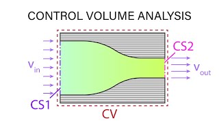
Control Volume Considerations
In this section, we delve into control volume analysis, crucial for understanding fluid dynamics. A control volume is a defined volume through which fluid flows, allowing for mass and momentum conservation. Key concepts include:
- Mass and Momentum Conservation: The application of mass conservation equations (A1V1 = A2V2 for incompressible flow) and momentum equations governs fluid motion in control volumes.
- Bernoulli’s Equations: When analyzing flow through control volumes, Bernoulli’s principle helps quantify energy losses due to friction and other factors.
- Valve Types: Various valve types, such as gate valves and globe valves, are examined, highlighting their role in flow regulation and energy loss through vortex formations in the fluid stream.
- Energy Loss Calculations: The section further outlines the derivation of energy losses using Bernoulli's equation and control volume analysis, accounting for both major (friction) and minor losses (from components like valves).
- Visualizing Flow and Energy Lines: The hydraulic and energy gradient lines provide insights into energy availability at different points in a flow system, illustrating how pumps and friction affect overall flow performance.
This analysis is fundamental for engineers tasked with designing efficient fluid systems.
Youtube Videos


Audio Book
Dive deep into the subject with an immersive audiobook experience.
Understanding Control Volumes
Chapter 1 of 6
🔒 Unlock Audio Chapter
Sign up and enroll to access the full audio experience
Chapter Content
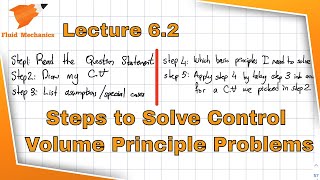
If you try to understand that or try to draw that sketch you solve the 20% of the problems, another 20 I can say not the 20% maybe 50% of problems. Another 50% is that how to apply mass conservations equations, linear momentum equations and the Bernoulli’s equations which it is not that difficult to apply it. So the basically the strategy is that you should try to understand these ones.
Detailed Explanation
This chunk introduces the fundamental concepts of control volumes, emphasizing their importance in solving problems related to fluid dynamics. Understanding control volumes involves recognizing areas of interest for analysis and applying conservation laws effectively. By breaking down complex problems into manageable parts, students can tackle 50% of their challenges by mastering these foundational equations and principles.
Examples & Analogies
Think of a control volume like a section of a busy street where you want to understand the flow of traffic. By observing specific points on the street, such as intersections (like mass and momentum in fluids), you can figure out how to manage and optimize the traffic flow, paralleling how control volumes help manage fluid behavior.
Valves and Flow Control
Chapter 2 of 6
🔒 Unlock Audio Chapter
Sign up and enroll to access the full audio experience
Chapter Content
If you look it that most of the times also we have a valve to control the flow okay which is a gate valve okay, it is a gate type of systems. If you rotate it this valve closes the waters okay. And it can have a total open or half closed and all these conditions to regulate the flow.
Detailed Explanation
This section discusses the role of valves, particularly gate valves, in controlling fluid flow. A gate valve operates by opening or closing to allow or restrict flow. The valve's position can be fully open, half closed, or closed, which affects how much fluid passes through. Understanding these operational modes is crucial for managing flow in system designs effectively.
Examples & Analogies
Imagine a water faucet in your home. Turning the handle adjusts how much water flows out, similar to how a gate valve works. If you turn it halfway, water flows but not at full speed; if you turn it fully, water gushes out. This control is essential for both household usage and mechanical systems.
Effects of Valve Position on Flow Patterns
Chapter 3 of 6
🔒 Unlock Audio Chapter
Sign up and enroll to access the full audio experience
Chapter Content
Now if you look it if I am to draw the streamlines, how it happens it. So streamlines will come like this okay. There could be vortex formations. And if you try to understand it, that I have not this open or the totally close, if the half open your flow distributions you can understand it how the streamlines patterns will come, how the vortex formations will have.
Detailed Explanation
This chunk addresses the impact of valve position on fluid flow patterns. It highlights that streamlines, which show the path of fluid particles, change based on whether the valve is fully open, partially open, or closed. This affects how the fluid behaves around the valve, often resulting in the formation of vortices which can lead to energy dissipation and turbulent flow. Understanding these patterns is essential for analyzing and optimizing flow systems.
Examples & Analogies
Imagine a river that flows smoothly when there are no obstacles (like a fully open valve). However, when you place rocks in the river (similar to a closed or partly closed valve), the water swirls around them, creating eddies (vortices). This analogy illustrates how controlling an opening can significantly alter the flow characteristics in a system.
Energy Losses in Flow Systems
Chapter 4 of 6
🔒 Unlock Audio Chapter
Sign up and enroll to access the full audio experience
Chapter Content
Let us come for derivations of energy losses and the pressure and velocity distributions of having a systems where two pipes we are enlarging it from the smaller diameter to bigger diameters. If you have that conditions and you can draw the velocity distributions. The velocity distribution it depends upon the type of the flow. If I have a laminar flow, the velocity distribution is different.
Detailed Explanation
This chunk examines energy losses and flow characteristics in piping systems as the diameter changes. When fluid flows through pipes that widen from a smaller diameter to a larger one, the velocity distribution of the fluid varies. In laminar flow, the fluid flows in parallel layers with less turbulence, hence it has a different distribution than turbulent flow, which is chaotic and mixed. Understanding these concepts helps in predicting system performance and guiding design decisions.
Examples & Analogies
Think of water flowing through a garden hose. When the hose is narrow (small diameter), the water rushes out quickly (high velocity). If you switch to a wider section of the hose, the water moves more slowly (low velocity) but can carry more overall flow. This situation reflects how pipe diameter affects fluid behavior in engineering systems.
Applying Bernoulli's Equation
Chapter 5 of 6
🔒 Unlock Audio Chapter
Sign up and enroll to access the full audio experience
Chapter Content
Now I will applying Bernoulli’s equations along the straight line, okay I am just applying the Bernoulli’s equation along the straight line. When you apply the Bernoulli’s equations, this line is horizontal. This streamline is horizontal, so you do not have a z components. You have pressure head component and the velocity head component.
Detailed Explanation
This chunk focuses on the application of Bernoulli's equation in analyzing fluid flow along a horizontal streamline. The equation relates pressure, velocity, and height (potential energy). In a horizontal case, changes in elevation (z components) are not considered, allowing for a simplified analysis of pressure head and velocity head. This understanding is foundational in fluid mechanics as it allows engineers to quantify energy losses and flow characteristics in various contexts.
Examples & Analogies
Imagine you're riding a bike down a flat road. The faster you pedal (increased velocity), the less you're likely to feel the pressure of wind against you (decreased pressure). Bernoulli's principle describes this relationship, like how pressure and velocity interchange to maintain a balance in energy.
Hydraulic and Energy Gradient Lines
Chapter 6 of 6
🔒 Unlock Audio Chapter
Sign up and enroll to access the full audio experience
Chapter Content
Again I am repeating it this energy gradient line and hydraulic gradient line what we discussed just after the Bernoulli’s equations. Now let us I have the reservoir, okay. This is the datum. From the reservoirs I have the pipe systems okay and there is a pumping system.
Detailed Explanation
In this chunk, the concept of energy and hydraulic gradient lines is introduced. These lines represent the total energy available at different points in a fluid system, helping visualize how energy changes due to hydraulic control features. The hydraulic gradient incorporates pressure and elevation, while the energy gradient reflects overall energy losses, allowing for effective monitoring of system performance.
Examples & Analogies
Visualize a water reservoir at the top of a hill with pipes leading down. As water flows through the pipes, its potential energy (due to height) decreases. If there’s a pump, it adds energy (pushing water higher or faster). Drawing energy and hydraulic gradient lines is like charting how those energy levels change as water flows from the top of the hill downwards – a vital tool for engineers designing effective systems.
Key Concepts
-
Control Volumes: Defined regions for analyzing fluid behavior.
-
Mass Conservation: Essential principle stating mass remains constant in flow.
-
Momentum Equations: Formulas relating forces and motion in fluid mechanics.
-
Bernoulli’s Equation: Fundamental relation of energy conservation in fluids.
-
Energy Loss: Loss of useful energy in the flow due to friction or turbulence.
Examples & Applications
A system with a block valve leading to a change in flow velocity, demonstrating energy loss at various intervals.
Using Bernoulli's equation to calculate pressure drops across different sections of piping with varying diameters.
Memory Aids
Interactive tools to help you remember key concepts
Rhymes
In the flow, friction slows, energy loss always shows.
Stories
Imagine a river where the water splits into streams, each choosing a path shaped by valves; some free, some restricted, like the journey of a flow.
Memory Tools
Remember 'Mass is Momentum, Pressure is Key' to recall the core principles.
Acronyms
V.R.P.E.
Valves
Reynolds
Pressure
Energy to remember key fluid dynamics concepts.
Flash Cards
Glossary
- Control Volume
A defined space through which fluid flows, allowing the analysis of mass and momentum conservation.
- Mass Conservation
A principle stating that mass cannot be created or destroyed in a closed system, mathematically represented as A1V1 = A2V2.
- Bernoulli’s Equation
An equation that relates pressure, velocity, and elevation in flowing fluids, incorporating energy losses.
- Valve Types
Mechanical devices used to control the flow of fluids; types include gate and globe valves, each affecting energy efficiency differently.
- Energy Loss
The reduction in available energy due to factors like friction and turbulence during fluid movement.
Reference links
Supplementary resources to enhance your learning experience.