
Velocity Distributions
Enroll to start learning
You’ve not yet enrolled in this course. Please enroll for free to listen to audio lessons, classroom podcasts and take practice test.
Interactive Audio Lesson
Listen to a student-teacher conversation explaining the topic in a relatable way.
Introduction to Velocity Distributions
🔒 Unlock Audio Lesson
Sign up and enroll to listen to this audio lesson

Today, we'll discuss velocity distributions in fluid flow. Velocity is how fast the fluid moves, which is critical to many applications in engineering.

What do you mean by velocity distributions?
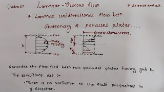
Great question! Velocity distributions refer to how the speed of fluid varies across a certain area, particularly in pipes. For instance, in laminar flow, the velocity is highest at the center and decreases towards the pipe wall.

And what about turbulent flow? Is it different?
Absolutely! In turbulent flow, velocities are more chaotic and mixed, meaning there isn't a smooth profile like in laminar flow. Think of turbulent flow as a fast river with swirling eddies.

How do we apply mass conservation in this context?
Great insight! We apply the principle of mass conservation in fluid flow using the equation A1V1 = A2V2, where A is the cross-sectional area and V is the fluid velocity. This helps us understand how velocity changes with varying pipe diameters.

Can you summarize what we discussed?
Sure! We discussed velocity distributions, the difference between laminar and turbulent flows, and how mass conservation equations govern fluid motion in pipes.
Flow Control Devices
🔒 Unlock Audio Lesson
Sign up and enroll to listen to this audio lesson

Let's talk about flow control devices, especially valves. Valves like gate valves and globe valves control fluid flow. Can anyone explain the difference?
I think gate valves are used to fully open or close the flow, while globe valves provide finer control.
Exactly! Gate valves are more efficient for full-flow applications, while globe valves create more resistance and energy loss.
What’s the impact of half-open conditions?
When partially open, both types can cause vortex formations and increased energy losses because of the unsteady flow patterns. This can be crucial in design considerations.
How do we calculate those energy losses?
We can use the modified Bernoulli's equation, which takes into account head losses due to friction and any restrictions caused by valves and pipe diameters.
Could you explain head loss?
Sure! Head loss is the reduction in total hydraulic energy of the fluid due to friction, turbulence, or obstructions.
Energy and Hydraulic Gradients
🔒 Unlock Audio Lesson
Sign up and enroll to listen to this audio lesson
Now, let's discuss energy and hydraulic gradient lines. These lines are essential in visualizing how energy is distributed in a pipe system.
How do they differ?
The energy gradient line includes all forms of energy in the system, while the hydraulic gradient line focuses more on pressure head, taking into account elevation changes.
Can we sketch these lines, or is it complex?
Sketching them is not only possible but essential! By plotting these lines, we can assess the efficiency of a pipeline and identify potential energy losses.
What happens to these lines with a pump in the system?
A pump will increase the energy gradient line due to enhancing pressure and velocity, effectively raising the energy available for flow.
Can you conclude what we've learned in this session?
Absolutely! We've covered energy and hydraulic gradient lines and their implications for pipe design and understanding fluid flow behavior.
Introduction & Overview
Read summaries of the section's main ideas at different levels of detail.
Quick Overview
Standard
The section emphasizes the importance of understanding velocity distributions impacted by laminar and turbulent flows, alongside the application of conservation laws and energy equations to assess energy losses in various flow control devices, like gate and globe valves.
Detailed
In this section, we delve into the concept of velocity distributions in fluid dynamics, highlighting the significance of understanding mass conservation, linear momentum equations, and Bernoulli’s equations. The section illustrates how different valve types, such as gate valves and globe valves, affect flow patterns and energy losses due to their design. It is crucial to comprehend how the geometry of a piping system, from smaller to larger diameters, influences velocity distributions and energy losses. We explore terms like laminar and turbulent flow, the importance of vortex formations, and the derivation of energy losses in various operating conditions. By incorporating examples, we derive insights into flow dynamics, including the implications of varying pipe dimensions on fluid velocity and pressure. Additionally, the section underscores the relevance of the energy and hydraulic gradient lines in understanding the system’s behavior under different flow conditions.
Youtube Videos


Audio Book
Dive deep into the subject with an immersive audiobook experience.
Understanding Flow Control Using Valves
Chapter 1 of 7
🔒 Unlock Audio Chapter
Sign up and enroll to access the full audio experience
Chapter Content
If you look it that most of the times also we have a valve to control the flow okay which is a gate valve okay, it is a gate type of systems. If you rotate it this valve closes the waters okay. And it can have a total open or half closed and all these conditions to regulate the flow to regulate the flow we have a these systems.
Detailed Explanation
In fluid mechanics, valves are essential for controlling the flow of fluids within pipes. A gate valve operates by moving a gate (or disc) up and down to either allow water to flow freely or block the flow completely. It can also be partially opened, which allows for a regulated flow rate. Understanding how these valves work is crucial because they can affect the pressure and velocity of the fluid in the pipes they control.
Examples & Analogies
Imagine a garden hose connected to a faucet. If you turn the faucet all the way on, the water flows freely, similar to a fully opened valve. If you turn the faucet halfway, the water flow reduces, akin to a valve that's partially opened. Just like adjusting the faucet control can modify the garden’s water pressure and flow, valves in industrial systems regulate fluid behavior in large-scale operations.
Streamlines and Flow Patterns
Chapter 2 of 7
🔒 Unlock Audio Chapter
Sign up and enroll to access the full audio experience
Chapter Content
Now if you look it if I am to draw the streamlines, how it happens it. So streamlines will come like this okay. There could be the vortex formations. And if you try to understand it, that I have not this open or the totally close, if the half open your flow distributions you can understand it how the streamlines patterns will come, how the vortex formations will have.
Detailed Explanation
Streamlines are a way to visualize the flow of fluid around objects, showing the direction and speed of the fluid. When we adjust a valve (fully open, partially open, or closed), the pattern of these streamlines changes, which in turn affects how the fluid moves and whether vortices (swirling flows) form. When fluid flows over an object, it can separate from the surface, creating regions of lower pressure known as vortices that can impact flow efficiency and energy loss.
Examples & Analogies
Think of how a finger partially blocking the end of a running garden hose changes the water's movement. When the hose is unrestricted, the flow is smooth (like a fully opened valve). When your finger is placed at the opening, it creates turbulent flow and splashes, resembling vortex formations. This analogy helps illustrate how flow distributions change based on the openness of a valve and how that impacts fluid behavior.
Differentiating between Globe Valves and Gate Valves
Chapter 3 of 7
🔒 Unlock Audio Chapter
Sign up and enroll to access the full audio experience
Chapter Content
Now if you look it similar way we have a the globe valve which is more control valve systems. The flow comes here, then rotate it and this valve it goes off and flow goes like this. So we can look it now in terms of vortex formations here, the vortex formations here, and once flow goes it also could have the vortex formations also here.
Detailed Explanation
Globe valves differ from gate valves in their design and function. They are designed for better control of flow and pressure, often producing more resistance compared to gate valves. When the fluid passes through a globe valve, it may cause more turbulence and vortices due to the way the valve geometry changes the flow path, resulting in different energy losses compared to gate valves.
Examples & Analogies
Consider how different types of faucets work in your kitchen. A faucet with a rotating mechanism (like a globe valve) can adjust water pressure more finely than one that simply opens and closes (like a gate valve). When you want a gentle flow to fill a cup, the globe valve allows for a smooth modulation of water flow, preventing splashes and maintaining a steady stream, just as how the globe valve works to manage the flow in a pipe system.
Energy Losses and Pressure Distribution
Chapter 4 of 7
🔒 Unlock Audio Chapter
Sign up and enroll to access the full audio experience
Chapter Content
Let us come for derivations of energy losses and the pressure and velocity distributions of having a systems where two pipes we are enlarging it from the smaller diameter to bigger diameters.
Detailed Explanation
When discussing energy losses in fluid systems, it's important to understand that these losses can occur due to various reasons, often linked to the geometry of the pipes involved. As fluid moves from a smaller diameter pipe to a larger one, the velocity typically decreases, affecting the pressure distribution along the pipe. This relationship is influenced by whether the flow is laminar or turbulent, each having distinct velocity distribution characteristics.
Examples & Analogies
Think about drinking through a straw. If the straw is narrow, you need to suck harder (imposing more energy) to get the fluid out. However, if you switch to a wider straw, the fluid flows out effortlessly. The energy you exert is less with a larger straw because you experience less resistance, similar to when fluids transition from a smaller to a larger pipe diameter.
Applying Bernoulli's Equation
Chapter 5 of 7
🔒 Unlock Audio Chapter
Sign up and enroll to access the full audio experience
Chapter Content
Now I will applying Bernoulli’s equations along the straight line, okay I am just applying the Bernoulli’s equation along the straight line.
Detailed Explanation
Bernoulli's equation relates pressure, velocity, and height in a flowing fluid, making it particularly useful in analyzing fluid dynamics in various engineering applications. When applying this equation along a streamline in a horizontal flow, we consider the pressure head and velocity head while neglecting elevation changes. The equation helps quantify energy losses due to friction and other factors throughout the flow system.
Examples & Analogies
Imagine you’re sliding down a water slide. As you go down (increasing velocity), you feel that rush of wind against your face; that’s similar to how velocity and pressure interact in fluid flow according to Bernoulli's principle. The exciting feeling of speed comes from energy conversion, where gravitational potential energy converts to kinetic energy - echoing the concepts in Bernoulli’s equations.
Understanding Hydraulic Gradient Lines
Chapter 6 of 7
🔒 Unlock Audio Chapter
Sign up and enroll to access the full audio experience
Chapter Content
Again I am repeating it this energy gradient line and hydraulic gradient line what we discussed just after the Bernoulli’s equations. Now let us I have the reservoir, okay. This is the datum. From the reservoirs I have the pipe systems okay and there is a pumping system.
Detailed Explanation
The hydraulic gradient line represents the total potential energy available to the fluid at various heights along a pipeline, taking into account both pressure and elevation. The energy gradient line, on the other hand, incorporates the flow velocity and other losses, providing insights into how energy is distributed within the fluid system. Understanding these concepts helps engineers design more efficient fluid systems.
Examples & Analogies
Picture a mountain river: the higher you are on the mountain, the greater the potential energy of the water (hydraulic gradient). As the river flows downhill, it loses energy (reflected in our energy gradient line) through friction and other factors. Engineers study these lines to construct water systems that ensure water gets to homes and businesses efficiently, much like understanding the river’s flow helps keep it from flooding or drying up.
Application and Importance of Velocity Distributions
Chapter 7 of 7
🔒 Unlock Audio Chapter
Sign up and enroll to access the full audio experience
Chapter Content
So now let us come to the questions okay, the examples what we have.
Detailed Explanation
Understanding velocity distributions is critical for predicting how fluids behave in different conditions. Engineers and scientists use it to solve real-life problems, from designing piping systems to ensuring adequate water pressure in infrastructure. By applying the concepts of conservation of mass and momentum along with Bernoulli’s equations, they can make informed decisions that affect efficiency and safety in fluid systems.
Examples & Analogies
Consider traffic patterns on a busy highway: just as engineers analyze how cars move together in lanes, predicting where bottlenecks may occur, fluid dynamics experts analyze how liquid flows through pipes. By understanding velocity distributions in both cases, they can design better systems for smooth traffic and efficient fluid delivery, helping society function effectively.
Key Concepts
-
Velocity Distribution: The speed of fluid can vary across different areas.
-
Laminar Flow: Characterized by smooth, layered motion.
-
Turbulent Flow: Features chaotic fluid movement with mixing and swirling.
-
Mass Conservation: Essential principle governing fluid flow, indicating that mass is conserved.
-
Bernoulli’s Equation: A fundamental equation connecting pressure, velocity, and height.
Examples & Applications
In a pipe with varying diameters, fluid velocity increases in a narrower section due to mass conservation.
When using a globe valve, more energy is lost compared to a gate valve due to the tighter control and higher resistance to flow.
Memory Aids
Interactive tools to help you remember key concepts
Rhymes
In pipes so wide and narrow too, velocity shifts like the breeze that blew.
Stories
Once there was a calm river where the flow was smooth and predictable (laminar), but when the storm came, it became wild and turbulent, swirling in every direction!
Memory Tools
Remember: Laminar flows Layer, Turbulent flows Twirl!
Acronyms
FLOW = Fluid Layering Operates with Water
Flash Cards
Glossary
- Velocity Distribution
The variation of fluid velocity at different points across a flow path.
- Laminar Flow
A smooth, orderly flow regime where fluid moves in parallel layers.
- Turbulent Flow
A chaotic flow regime characterized by mixing and eddies.
- Mass Conservation
A principle stating that mass cannot be created or destroyed in a closed system.
- Bernoulli’s Equation
A principle that relates the pressure, velocity, and height of a fluid in steady flow.
- Head Loss
The energy loss due to friction, turbulence, or obstructions in a flowing fluid.
Reference links
Supplementary resources to enhance your learning experience.