
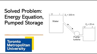
Derivations of Energy Losses
Enroll to start learning
You’ve not yet enrolled in this course. Please enroll for free to listen to audio lessons, classroom podcasts and take practice test.
Interactive Audio Lesson
Listen to a student-teacher conversation explaining the topic in a relatable way.
Introduction to Energy Losses
🔒 Unlock Audio Lesson
Sign up and enroll to listen to this audio lesson

Welcome, everyone! Today we'll discuss energy losses in fluid systems. Can anyone tell me why it’s important to consider energy losses?

I think it's essential because it impacts the efficiency of pumps and systems!
Exactly! Energy losses can greatly affect performance. Now, energy loss can result from several factors including the flow type. Can anyone name those types?

I believe there are laminar and turbulent flows?
Correct! Laminar flows are smooth and orderly, while turbulent flows are chaotic. We'll encounter different loss equations for each. Just remember: if we acronymize that, we can use 'LOT' for Laminar, Orderly, and Turbulent.
Valves and Their Impacts
🔒 Unlock Audio Lesson
Sign up and enroll to listen to this audio lesson

Let’s move to valves—specifically, the gate valve and the globe valve. Who can describe how a gate valve works?

A gate valve opens and closes to control water flow, right? It can be fully open or partially closed!
Great summary! Partial closure indeed leads to increased energy dissipation. Does anyone remember how a globe valve differs?

It provides more control over flow regulation than a gate valve!
Exactly! Because of this control, globe valves often have higher energy loss due to their design. Let’s keep that in mind as we calculate energy losses using Bernoulli's equation.
Applying Bernoulli's Equation
🔒 Unlock Audio Lesson
Sign up and enroll to listen to this audio lesson
Now, we need to apply Bernoulli's equation to quantify energy losses. What does Bernoulli's equation tell us, specifically?
It relates the pressure head, velocity head, and potential head in a flowing fluid.
Exactly! When we incorporate energy losses into this equation, we’re essentially deriving a modified version. Why do you think we do this?
To account for the energy dissipated due to friction and other losses, right?
Right! This leads to a more accurate representation of energy available at different points in a system.
Calculating Head Losses
🔒 Unlock Audio Lesson
Sign up and enroll to listen to this audio lesson
We can derive head losses using simplified equations based on what we have learned. Can anyone explain what factors affect these losses?
Pipe diameter, flow velocity, and type of fittings, such as elbows or junctions?
Perfect! The K factor for these fittings will help us quantify energy losses effectively. Remember, wider pipes generally reduce losses, while sharper fittings increase them.
Introduction & Overview
Read summaries of the section's main ideas at different levels of detail.
Quick Overview
Standard
In this section, the derivations of energy losses in fluid systems are explored, focusing on the impact of various valve types, flow conditions, and applying conservation equations like mass conservation and Bernoulli's equation to understand energy loss calculations.
Detailed
In this section, we delve into the derivations of energy losses in hydraulic systems and discuss how these concepts apply to real-world applications. Understanding energy losses is crucial for making efficient designs in fluid systems. The discussion highlights various factors that contribute to energy losses, including the nature of the flow (laminar vs turbulent), valve types such as gate and globe valves, and the role of mass conservation equations in fluid mechanics. We explore the implications of these factors through Bernoulli's equation, noting how energy losses can be computed based on flow conditions and valve configurations using derived equations. The section underlines the importance of sketching energy and hydraulic gradient lines to visualize energy distributions within piping systems.
Youtube Videos


Audio Book
Dive deep into the subject with an immersive audiobook experience.
Understanding Energy Losses in Flow Systems
Chapter 1 of 5
🔒 Unlock Audio Chapter
Sign up and enroll to access the full audio experience
Chapter Content
Let us come for derivations of energy losses and the pressure and velocity distributions of having a systems where two pipes we are enlarging it from the smaller diameter to bigger diameters. If you have that conditions and you can draw the velocity distributions. The velocity distribution it depends upon the type of the flow. If I have a laminar flow, the velocity distribution is different. If I have a turbulent flow velocity distributions is different.
Detailed Explanation
This chunk discusses the initial concepts of energy losses in pipe flow systems. In particular, when fluid flows through pipes of varying diameters, the velocity distribution is affected. If the flow is laminar (smooth and orderly), it behaves differently compared to turbulent flow (chaotic and irregular). Understanding these distributions is critical for analyzing energy losses. A laminar flow generally offers less energy loss than turbulent flow due to the less chaotic motion of the molecules in the fluid.
Examples & Analogies
Think of a calm river (laminar flow) versus a fast-moving rapids (turbulent flow). In the calm river, water flows smoothly without much disturbance. In contrast, the rapids create numerous waves and turbulence which would suggest higher energy loss due to friction with surfaces and chaotic interactions among water molecules.
Applying Control Volume Concepts
Chapter 2 of 5
🔒 Unlock Audio Chapter
Sign up and enroll to access the full audio experience
Chapter Content
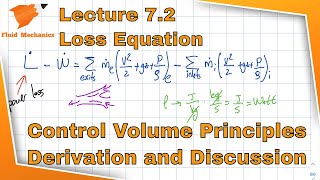
Now coming to this, I am just applying the linear momentum equations for these control volumes. If you have this is the control volumes. So you may have the shear stress is acting on this okay, this the shear stress part, okay. But we are neglecting this part, we are neglecting the shear stress part. Just we are assuming the pressure difference between these is equate with a momentum flux.
Detailed Explanation
This section discusses the application of linear momentum equations to control volumes in a flow system. It highlights how shear stress, which usually contributes to energy loss, is neglected in some cases to simplify calculations. Here, the pressure difference is equated with momentum flux, allowing us to relate pressure changes to fluid momentum, which is important in energy loss analysis.
Examples & Analogies
Imagine blowing air through a narrow straw (control volume). The pressure change you feel when you start blowing is similar to the pressure difference in the fluid. As you blow harder, the momentum (speed) of air increases, resulting in a change in pressure at the end of the straw, just like how momentum changes apply to fluid flows in pipes.
Utilizing Bernoulli’s Equation
Chapter 3 of 5
🔒 Unlock Audio Chapter
Sign up and enroll to access the full audio experience
Chapter Content
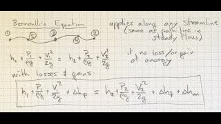
Now I will applying Bernoulli’s equations along the straight line, okay I am just applying the Bernoulli’s equation along the straight line. When you apply the Bernoulli’s equations, this line is horizontal. This streamline is horizontal, so you do not have a z components. You have pressure head component and the velocity head component.
Detailed Explanation
This part details the application of Bernoulli's equation, which describes the principle of energy conservation in fluid flows. By considering the horizontal streamline, we can analyze how pressure and velocity heads contribute to energy transfer across sections of flow. The concept simplifies calculations by assuming no vertical elevation changes, focusing solely on pressure and velocity influences on energy losses.
Examples & Analogies
Consider a garden hose that's slightly elevated near the nozzle. When you apply pressure at the handle, water flows quickly out of the nozzle, decreasing pressure inside the hose. Bernoulli's principle helps us understand how the energy conservation between pressure and flow speed works, showcasing how energy is transformed rather than lost.
Energy Loss Quantification
Chapter 4 of 5
🔒 Unlock Audio Chapter
Sign up and enroll to access the full audio experience
Chapter Content
So the flow is come from the one section to sections two where through the flow there is energy losses, that is what we quantify. So because of that we call it is a modified Bernoulli’s equation which is nothing else. You are equating the energy, you know that how much of energy losses has happened.
Detailed Explanation
In this segment, the focus shifts to quantifying energy losses due to flow transitions from one section to another. This is encapsulated in the modified Bernoulli’s equation, which takes into account these losses by including terms that represent the energy dissipated within the system. Understanding this quantification is vital for managing energy within fluid systems.
Examples & Analogies
Imagine riding a bike on a flat road and then going uphill. The effort expended to climb that hill represents energy loss due to gravity. Similarly, when fluid moves through pipes, energy is dissipated, requiring us to account for that loss to maintain efficiency, akin to adjusting our pedaling effort to cope with the incline.
Calculating Losses for Pipe Types
Chapter 5 of 5
🔒 Unlock Audio Chapter
Sign up and enroll to access the full audio experience
Chapter Content
The same way if you have a gradually contractions happening it or gradual enlargement that you can compute this values. For gradual contraction or for gradual enlargement, the friction factor K is given by...
Detailed Explanation
This chunk introduces how to calculate friction factors (K) for pipes experiencing gradual changes in diameter. The friction factor is a crucial parameter as it significantly influences the total energy losses in a pipe flow. Understanding how to calculate and apply this friction factor helps in designing efficient piping systems and predicting energy losses when the diameter changes.
Examples & Analogies
Think about drinking from a funnel. As the liquid passes through the narrower end (gradual contraction), it experiences more friction, just like a pipe. The same principle applies in wider pipes where gradual enlargements can also affect flow characteristics. By knowing how to calculate these changes, we can better manage fluid flow.
Key Concepts
-
Energy Losses: Loss of energy due to friction and turbulence in fluid systems.
-
Bernoulli's Equation: A mathematical tool for analyzing fluid flow.
-
Laminar vs Turbulent Flow: Different behaviors of fluid motion impacting energy loss.
-
Valves: Devices that control fluid flow and contribute to energy losses.
-
K Factor: Coefficient representing losses due to fittings.
Examples & Applications
Valves such as gate and globe valves exhibit significant differences in energy losses based on their design and usage.
Using Bernoulli's equation allows engineers to quantify energy losses in fluid systems and design more efficient piping layouts.
Memory Aids
Interactive tools to help you remember key concepts
Rhymes
Friction steals the flow, energy loss is what we know.
Stories
Imagine a river flowing fast; when it bumps into a stone, energy scatters at last. The flow smoothes out as it moves away. This tells us energy friction will always stay.
Memory Tools
Remember the acronym 'FVLK' for Flow types, Valves, Losses, K factors.
Acronyms
Use 'FLOW' to recall
Friction
Losses
Optimization
and Water.
Flash Cards
Glossary
- Energy Losses
The loss of mechanical energy in a fluid system due to factors like friction, turbulence, and changes in geometry.
- Bernoulli's Equation
A principle that describes the relationship between pressure, velocity, and height in a flowing fluid, often used to analyze fluid dynamics.
- Laminar Flow
A type of flow characterized by smooth and orderly fluid motion, typically occurring at lower velocities.
- Turbulent Flow
Flow characterized by chaotic and irregular fluid motion, occurring at higher velocities.
- K Factor
A coefficient that quantifies the energy losses due to fittings and valves in a fluid system.
Reference links
Supplementary resources to enhance your learning experience.