
Head Loss Calculations
Enroll to start learning
You’ve not yet enrolled in this course. Please enroll for free to listen to audio lessons, classroom podcasts and take practice test.
Interactive Audio Lesson
Listen to a student-teacher conversation explaining the topic in a relatable way.
Understanding Valves and their Impact on Flow
🔒 Unlock Audio Lesson
Sign up and enroll to listen to this audio lesson

Today we're going to discuss how valves influence the flow of fluids and subsequently affect head loss. Can anyone tell me why understanding flow patterns is important?

Is it because it helps in predicting energy losses?
Exactly! By drawing flow patterns, we can visualize energy losses. Valves like gate valves can create significant energy dissipation, especially when partially closed. Work with the acronym 'FLOW' – 'Friction Loss Observed with Valves.'

What about the globe valve? How is it different?
Good question! Globe valves allow for better flow control than gate valves, but they also incur a higher energy loss. Always remember, comparing losses helps in deciding the right valve for specific applications.
Applying Bernoulli’s Equation
🔒 Unlock Audio Lesson
Sign up and enroll to listen to this audio lesson

Now, let’s apply Bernoulli’s equation to analyze energy losses due to friction. Can someone summarize the basics of Bernoulli’s principle?

It states that the total mechanical energy along a streamline is constant, accounting for kinetic energy, potential energy, and pressure energy.
Correct! When we account for energy losses, we modify Bernoulli's equation to include terms for head loss. Remember this equation for losses: 'H_loss = K * (v^2 / 2g)'. What does K represent here?

K is the energy loss coefficient, right? It varies with the type of valve or pipe geometry.
Exactly! Understanding K helps quantify losses efficiently. Let's ensure we practice this concept with real examples.
Velocity Distributions and Flow Types
🔒 Unlock Audio Lesson
Sign up and enroll to listen to this audio lesson
Next, let’s discuss how the type of flow impacts velocity distribution. Can anyone expand on the differences between laminar and turbulent flow?
Laminar flow is smooth and orderly, while turbulent flow is chaotic and irregular.
That's right! The velocity distribution for laminar flow forms a parabolic profile, whereas turbulent flow has a flatter profile. Use the mnemonic 'LAM' for Laminar And Messy for Turbulent flows!
Why does this matter for head loss calculations?
Great inquiry! The friction factor changes based on flow type, which directly influences head loss calculations. This is significant when analyzing energy loss through apparatus.
Energy Gradient and Hydraulic Gradient Lines
🔒 Unlock Audio Lesson
Sign up and enroll to listen to this audio lesson
Let’s visualize the energy and hydraulic gradient lines. Why do you think it’s important to sketch these in real-world applications?
It helps see how energy is distributed across a system and where losses occur.
Exactly! Consider these lines while designing pipes; they can highlight points of significant loss. 'EHP = Energy Heads in Pipes' for energy gradient helps you remember.
So, if we notice a steep drop in the hydraulic gradient, it indicates higher losses?
Right on target! Monitoring these slopes allows predictive analysis in design and operations.
Introduction & Overview
Read summaries of the section's main ideas at different levels of detail.
Quick Overview
Standard
In this section, the concept of head loss in fluid flow is explored in-depth, focusing on how different obstacles such as valves influence flow patterns and energy dissipation. By understanding mass conservation and Bernoulli’s equations, students can derive key energy loss equations central to fluid mechanics.
Detailed
Head Loss Calculations
In fluid dynamics, the calculation of head loss due to various factors like valves and pipe configurations is crucial in system design. This section begins by establishing that understanding and drawing flow patterns allows students to solve a significant portion of fluid dynamics problems.
A fundamental aspect introduced is the impact of valves, such as gate and globe valves, which are essential for controlling flow. The head loss associated with a valve can lead to increased energy dissipation; thus, evaluating their configuration becomes critical during fluid flow analysis.
As fluid transitions through pipes of varying diameters, changes in velocity distribution criteria are important to grasp. The section emphasizes the differences in behavior between laminar and turbulent flows, as these affect the calculations of energy within a control volume, which incorporates mass conservation and momentum equations. In incompressible fluid flow, the relationship between cross-sectional area and velocity becomes paramount (Av=constant).
Further, the section elaborates on applying Bernoulli’s equation to account for head losses due to friction and apparatus like valves and elbows. By introducing energy loss coefficients (K), students learn to quantify minor losses in terms of velocity head.
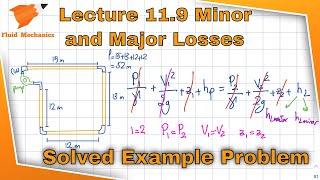
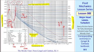
Finally, graphical representations of hydraulic and energy gradient lines illustrate how head losses manifest in practical systems. This culminates in utilization of classic fluid mechanics tools like Moody’s diagram to calculate friction factors, laying a foundational understanding crucial for advanced hydraulic system design.
Youtube Videos
![[MAE 242] Pipe flow with major and minor head losses](https://img.youtube.com/vi/WH1fn6dMYiw/mqdefault.jpg)


Audio Book
Dive deep into the subject with an immersive audiobook experience.
Understanding Energy Losses in Valves
Chapter 1 of 5
🔒 Unlock Audio Chapter
Sign up and enroll to access the full audio experience
Chapter Content
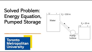
Let us come for derivations of energy losses and the pressure and velocity distributions of having systems where two pipes we are enlarging it from the smaller diameter to bigger diameters...
Detailed Explanation
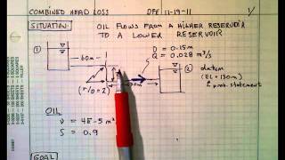
In fluid dynamics, when liquid flows through pipes, various factors such as pipe diameter, valve type, and flow conditions contribute to energy losses. For instance, when a pipe's diameter increases, the velocity of the fluid may decrease, and the pressure can change. These changes can lead to energy losses, primarily due to friction and turbulence. Understanding how to compute these losses is crucial for anyone designing fluid systems, as they affect efficiency and functionality.
Examples & Analogies
Imagine water flowing through a garden hose that suddenly widens at some point. The water will flow more slowly after the widening, resulting in some energy loss. If we had to water the garden quickly, we would want to minimize those losses to maintain sufficient pressure for effective watering.
Effects of Different Valve Types
Chapter 2 of 5
🔒 Unlock Audio Chapter
Sign up and enroll to access the full audio experience
Chapter Content
If you look at a similar way we have a globe valve which is a more control valve systems...
Detailed Explanation
Different types of valves affect fluid flow in varying ways. A globe valve, for instance, is designed for better control and offers higher resistance to flow, leading to more energy loss compared to a gate valve. This stems from the more convoluted path the liquid must take through the globe valve, which induces turbulence and friction, ultimately dissipating more energy.
Examples & Analogies
Think of two different paths to get to a destination: one is a straight road (gate valve), and the other has many curves and stops (globe valve). While both may get you to the same place, the straight road allows you to travel more efficiently, saving both time and fuel.
Using Bernoulli’s Equation for Energy Losses
Chapter 3 of 5
🔒 Unlock Audio Chapter
Sign up and enroll to access the full audio experience
Chapter Content
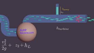
Now I will apply Bernoulli’s equations along the straight line, okay I am just applying Bernoulli’s equation along the straight line...
Detailed Explanation
Bernoulli's equation relates pressure, velocity, and height in a flowing fluid. When we incorporate energy losses into this equation, it becomes a modified form that allows us to account for head losses along a pipe. By comparing two points along the pipeline, we can quantify how much energy is lost due to friction and other factors, which is essential for maintaining the system's efficiency.
Examples & Analogies
Consider riding a bicycle down a straight path versus a bumpy one. On the bumpy path, you'll need to exert more energy to maintain speed due to friction and resistance. In a fluid system, the same principle applies, and we use Bernoulli’s equation to calculate how much energy we lose due to these 'bumps' in the flow.
Head Loss Calculation and K Factors
Chapter 4 of 5
🔒 Unlock Audio Chapter
Sign up and enroll to access the full audio experience
Chapter Content
Now if you look at the tabular values what we have and here I am talking about the head loss is equal to...
Detailed Explanation
Head loss is commonly expressed as a function of the velocity and the K-factor, which indicates how much energy is lost due to various components like valves and bends in the pipe system. By examining tables of K-factors for different fittings, engineers can predict energy losses and design more effective pipelines.
Examples & Analogies
Think of K-factors like a 'speed bump' measurement for pipes. Just as some speed bumps are taller and require more caution when driving over, some pipe fittings and valves impose more energy loss on the liquid flowing through them. Knowing the K-factor helps in determining how high these 'speed bumps' are in your piping system.
Energy and Hydraulic Gradient Lines
Chapter 5 of 5
🔒 Unlock Audio Chapter
Sign up and enroll to access the full audio experience
Chapter Content
Again I am repeating it this energy gradient line and hydraulic gradient line what we discussed just after the Bernoulli’s equations...
Detailed Explanation
The energy gradient line and hydraulic gradient line are critical for visualizing how energy changes throughout a fluid delivery system. The energy gradient line shows the total energy available at different points, while the hydraulic gradient line indicates the actual fluid pressure. Understanding both lines helps engineers design systems that ensure adequate pressure and flow rates.
Examples & Analogies
Imagine hiking up a hill. The total energy at any point can be seen as your physical ability to reach the top, while the hydraulic gradient is the incline of the path you're taking. If the incline is too steep (high hydraulic gradient), it may become too challenging to proceed, just as pressure changes can affect fluid flow in pipes.
Key Concepts
-
Head Loss: The energy lost due to friction in a fluid system.
-
Bernoulli’s Equation: A fundamental equation relating pressure, velocity, and height in fluid flow.
-
Flow Patterns: The paths followed by fluid in a system, critical for understanding energy loss.
-
Energy Loss Coefficient (K): A parameter quantifying energy loss due to components such as valves.
-
Laminar vs. Turbulent Flow: Distinct flow types characterized by the smoothness of fluid movement.
Examples & Applications
Example: Calculating head loss through a globe valve using the K value based on the valve's configuration.
Example: Applying Bernoulli’s equation to determine the pressure drop across a valve in a fluid system.
Memory Aids
Interactive tools to help you remember key concepts
Rhymes
For flow that’s smooth and neat, laminar you’ll greet. If it's turbulent, prepare for a chaotic street!
Stories
Once a calm river (laminar flow) flowed quietly. It suddenly turned chaotic (turbulent flow) with waves crashing over rocks, just like how different flow types behave in pipes.
Memory Tools
LAM for Laminar And Messy for Turbulent flow helps to remember their key characteristics.
Acronyms
FLOW = Friction Loss Observed with Valves outlines how valves influence fluid dynamics.
Flash Cards
Glossary
- Head Loss
The loss of energy in a fluid system due to friction and other impedances.
- Bernoulli’s Equation
An equation that relates the pressure, velocity, and elevation in a moving fluid.
- Flow Patterns
The visual representation of how fluid flow occurs in a system.
- Energy Loss Coefficient (K)
A factor used in calculations to quantify losses due to fittings and valves.
- Laminar Flow
A type of flow characterized by smooth, parallel layers of fluid.
- Turbulent Flow
Flow that is chaotic and characterized by vortices and eddies.
Reference links
Supplementary resources to enhance your learning experience.