
Globe Valve
Enroll to start learning
You’ve not yet enrolled in this course. Please enroll for free to listen to audio lessons, classroom podcasts and take practice test.
Interactive Audio Lesson
Listen to a student-teacher conversation explaining the topic in a relatable way.
Introduction to Globe Valves
🔒 Unlock Audio Lesson
Sign up and enroll to listen to this audio lesson

Today, we'll start by understanding the globe valve, a critical component for controlling fluid flow. Who can explain how a globe valve operates?

Isn't it designed to open and close by rotating a stem?
Exactly! The rotating mechanism allows for various positions from fully open to fully closed, which enables fine control over the flow rate.

How does it perform compared to a gate valve?
Great question! While gate valves are either fully open or closed, globe valves can be partially open. This makes globe valves better for flow regulation but they incur more energy losses.

What kinds of energy losses are we talking about?
We’ll get to that! But remember, higher energy losses occur with globe valves due to turbulent flow when they are partially open. Keep this in mind!
Flow Patterns and Energy Losses
🔒 Unlock Audio Lesson
Sign up and enroll to listen to this audio lesson

Next, let’s delve into flow patterns. When a globe valve is opened partially, what happens to the flow streamlines?

I think they become more chaotic, right? Like in turbulence?
Exactly! Vortex formations can lead to energy dissipation. Anyone remember how we can visualize these changes?
We can draw streamlines, right?
Yes! Drawing streamlines helps us understand how energy losses occur. It’s essential for applying Bernoulli's equation correctly!
What about when we change pipe diameters?
Good point! Different diameters lead to varied velocity distributions. We'll discuss those next!
Calculating Energy Losses
🔒 Unlock Audio Lesson
Sign up and enroll to listen to this audio lesson
Now onto calculations. When considering a control volume, how do we apply conservation of mass?
Is it through the equation A1V1 = A2V2?
Yes, correct! That represents mass flow rates across two sections. But also, we need to account for K factors due to fittings, like globe valves.
How does the K factor affect our calculations?
The K factor quantifies energy losses due to friction and other disturbances. The higher the K factor, the more energy loss.
So different valves have different K factors?
Exactly! Globe valves typically exhibit higher K factors than gate valves because of their construction and how they facilitate flow. Remember, more flow control can cost more energy.
Application of Bernoulli’s Equation
🔒 Unlock Audio Lesson
Sign up and enroll to listen to this audio lesson
Finally, let’s talk about applying Bernoulli’s equation. How do we include energy losses?
I think we subtract the head losses from the energy terms?
Correct! The modified Bernoulli’s includes terms for energy losses, which helps us calculate pressures and velocities at different points.
Can we see an example?
Absolutely! We’ll go through an example problem next class that illustrates how to derive pressures using Bernoulli’s equation with head loss. Make sure to think about how flow rates change!
Introduction & Overview
Read summaries of the section's main ideas at different levels of detail.
Quick Overview
Standard
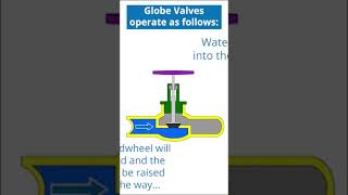
The section elaborates on how globe valves operate as flow control devices by managing water flow through their unique design, emphasizing the importance of understanding flow patterns, energy losses, and applying concepts from fluid dynamics like Bernoulli's equation and momentum equations. Comparisons between globe and gate valves are made, along with illustrations of their operational differences and implications for energy conservation.
Detailed
Detailed Summary
This section dives deep into the functioning and analysis of globe valves within fluid dynamics, particularly focusing on their utility in regulating flow. A globe valve controls flow by altering its opening mechanism, offering more precise control compared to gate valves, which are either fully open or closed. In contrast, globe valves can be partially closed, enabling nuanced flow management. The flow patterns resulting from different valve settings reveal critical aspects such as streamline behavior and vortex formation, which can lead to energy loss due to increased turbulence and flow disruption.
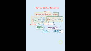
The chapter introduces essential equations such as the mass conservation equation and Bernoulli’s equation, which are crucial for analyzing energy exchanges within fluid systems with varying pipe diameters. The section illustrates how to draw streamlines to visualize flow behavior, highlighting the energy dissipation associated with various flow states—laminar versus turbulent.
In terms of operational mechanisms, the section explains calculating energy losses when different piping elements interact, emphasizing the importance of friction and pressure gradients in energy calculations. The section illustrates the significance of the K-factor, which characterizes energy losses through the different types of valves (like gate and globe valves), and contextualizes how different configurations (e.g., gradual vs. sudden contractions) influence flow and energy loss. Overall, the content provides a clear understanding of energy dynamics in piping systems, focusing on practical applications for fluid control.
Youtube Videos


Audio Book
Dive deep into the subject with an immersive audiobook experience.
Introduction to Globe Valves
Chapter 1 of 3
🔒 Unlock Audio Chapter
Sign up and enroll to access the full audio experience
Chapter Content
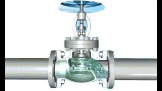
If you look it similar way we have a the globe valve which is more control valve systems. The flow comes here, then rotate it and this valve it goes off and flow goes like this.
Detailed Explanation
Globe valves are designed to control the flow of fluids through pipes. Unlike gate valves, which are primarily used for on/off control, globe valves allow for precise regulation of flow. When the valve is rotated, it either opens or closes, allowing the fluid to pass through or stopping it entirely. This mechanism makes globe valves suitable for applications where flow needs to be finely adjusted.
Examples & Analogies
Consider a garden hose: when you turn the nozzle, you can control how much water flows out. Similarly, a globe valve allows you to control the flow of fluid in a piping system, making it a key component in various engineering applications.
Vortex Formations with Globe Valves
Chapter 2 of 3
🔒 Unlock Audio Chapter
Sign up and enroll to access the full audio experience
Chapter Content
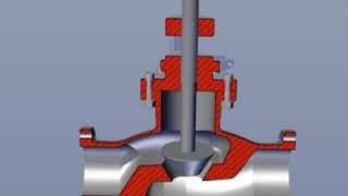
So we can look it now in terms of vortex formations here, the vortex formations here, and once flow goes it also could have the vortex formations also here.
Detailed Explanation
When fluid flows through a globe valve, the design can create vortex formations, which are swirling patterns in the flow. These vortices can lead to turbulence, increasing energy loss due to friction and altering pressure distribution within the system. Understanding these patterns is critical for engineers to minimize inefficiencies in fluid transport systems.
Examples & Analogies
Imagine when you swirl water in a bowl; it creates small whirlpools. In a valve, similar whirlpools can form, causing inefficient flow and energy loss, just like how it's harder to stir a soup with chunks compared to smooth broth.
Comparing Globe Valves and Gate Valves
Chapter 3 of 3
🔒 Unlock Audio Chapter
Sign up and enroll to access the full audio experience
Chapter Content
If you look it one is globe valve and the gate valve this require for different type of discharge conditions. So if you look at these conditions you can easily interpret it we will have a more energy losses for this case as compared to this ones.
Detailed Explanation
Globe valves and gate valves serve different purposes in flow control. While globe valves are better for regulating flow, they generally incur higher energy losses due to their design and the way they restrict flow. In contrast, gate valves are more efficient for fully open or closed positions, making them suitable for applications where minimal energy loss is desired.
Examples & Analogies
Think of a globe valve like a speed bump in a roadway; it slows down the flow of traffic to improve safety, whereas a gate valve is akin to a traffic light that allows smooth travel when open but completely stops it when closed.
Key Concepts
-
Flow Control: Globe valves allow for varying flow rates, enabling precise regulation of fluid movement.
-
Energy Loss: The flow through globe valves incurs higher energy losses due to turbulence, especially when partially open.
-
Bernoulli’s Equation: Essential for calculating energy changes in fluid systems, incorporating head losses due to fittings.
-
K Factor: A critical parameter that quantifies energy losses in valve systems, affecting overall system efficiency.
Examples & Applications
A globe valve controlling water flow in an industrial supply line can be adjusted to modulate the pressure and flow rate based on system demands.
When comparing a globe valve to a gate valve, the increased control capabilities of the globe valve come at the cost of higher energy losses, which must be accounted for in system design.
Memory Aids
Interactive tools to help you remember key concepts
Rhymes
When the globe is partially tight, energy flows lose their might!
Stories
Imagine a water delivery chef who can finely control how much water flows through a cooking pot. When the pot is fully open, the water flows freely, but when he starts to close it, the flow can become messy and less efficient—similar to how a globe valve operates.
Memory Tools
G.L.O.B.E: Gate-like Operations Bypass Energy losses - think of how gate valves differ in their flow control.
Acronyms
FLOW = Finesse for Liquid Operation with Valves - Remember that globe valves allow finesse in flow control.
Flash Cards
Glossary
- Globe Valve
A type of valve that controls fluid flow through a pipeline by varying the opening size.
- Gate Valve
A valve that opens or closes only fully, commonly used for on/off control.
- K Factor
Coefficient that quantifies energy loss due to fittings and components in fluid flow.
- Bernoulli's Equation
An equation that describes the conservation of energy in fluid flow.
- Turbulent Flow
A type of fluid flow characterized by chaotic changes in pressure and flow velocity.
- Streamlines
Lines that represent the direction of fluid flow; used to visualize flow patterns.
- Energy Loss
The reduction of mechanical energy in a fluid caused by friction and turbulence.
Reference links
Supplementary resources to enhance your learning experience.