
Combinational Circuit and Sequential Circuit Design using VHDL/Verilog
Interactive Audio Lesson
Listen to a student-teacher conversation explaining the topic in a relatable way.
Introduction to Combinational and Sequential Circuits
🔒 Unlock Audio Lesson
Sign up and enroll to listen to this audio lesson

Today, we will be discussing two main types of digital circuits: combinational and sequential circuits. What do you think sets them apart?

I think combinational circuits only depend on the current inputs.
That's correct! Combinational circuits output based solely on current inputs, while sequential circuits also consider past inputs.

So, sequential circuits can store information?
Exactly! This ability to store states allows sequential circuits to function as memory in various applications.

Can you give an example of a sequential circuit?
Certainly! Flip-flops are a classic example of sequential circuits. They capture the value of the input during a clock edge.
In summary, combinational circuits rely on current inputs only, while sequential circuits depend on both current inputs and past states.
Design of Combinational Circuits using VHDL
🔒 Unlock Audio Lesson
Sign up and enroll to listen to this audio lesson

Now, let's explore how we can design combinational circuits like an AND gate using VHDL. Who can tell me the entity structure?

I remember it has input and output ports defined.
Correct! The entity declaration specifies the inputs and outputs. Here's an example of a two-input AND gate in VHDL:
"```vhdl
Design of Sequential Circuits using Verilog
🔒 Unlock Audio Lesson
Sign up and enroll to listen to this audio lesson
Let's now move to sequential circuits and how we can create a D flip-flop using Verilog. Any idea how we start?
We need to declare the module and specify inputs and outputs.
Exactly! The module declaration details the inputs, which are the data and clock. Here's how it looks:
"```verilog
Finite State Machines (FSM) Design
🔒 Unlock Audio Lesson
Sign up and enroll to listen to this audio lesson
Lastly, let’s look into Finite State Machines, or FSMs. Does anyone know what an FSM is used for?
They model systems with a limited number of states!
Exactly! FSMs are pivotal in control systems and applications like traffic lights. Can someone describe how we might implement an FSM?
We define states and transitions based on inputs.
Right! We can use flip-flops with combinational logic to switch between states. Let’s summarize this: FSMs provide a structured approach to designing systems with specific states.
Introduction & Overview
Read summaries of the section's main ideas at different levels of detail.
Quick Overview
Standard
Combinational circuits depend solely on current inputs, while sequential circuits rely on both current inputs and previous states. The section details design principles and techniques for both types of circuits using VHDL and Verilog, illustrating concepts with specific examples such as adders and flip-flops.
Detailed
Detailed Summary
Combinational and sequential circuits are fundamental components of digital system design. Combinational circuits produce outputs based entirely on the present inputs, showcasing examples like adders, multiplexers, and logic gates. In contrast, sequential circuits incorporate memory, thus their outputs depend on both current inputs and past states, suitable for use in devices like flip-flops and counters.
This section provides comprehensive insights into the design of these circuits using two primary hardware description languages: VHDL and Verilog. Notably, it covers examples such as:
- Combinational Circuit Design: Includes VHDL/Verilog designs for basic elements like a two-input AND gate and a 4-bit full adder, demonstrating how to implement simple logical operations and arithmetic functionalities.
- Sequential Circuit Design: Discusses designs for D flip-flops and 4-bit counters in both VHDL and Verilog, showing how these circuits can retain state information through clocked input.
Moreover, the section elaborates on Finite State Machine (FSM) design, an important concept in designing control systems. The examples provided aim to illustrate practical applications and the structural differences between VHDL and Verilog implementations. The chapter concludes with a summary of key concepts, emphasizing the main differences between combinational and sequential circuits.
Youtube Videos


Audio Book
Dive deep into the subject with an immersive audiobook experience.
Introduction to Circuits
Chapter 1 of 5
🔒 Unlock Audio Chapter
Sign up and enroll to access the full audio experience
Chapter Content
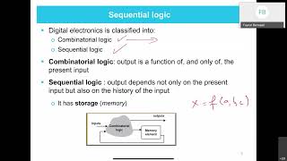
Combinational and sequential circuits are the two primary types of digital circuits used in system design. Combinational circuits are those whose outputs depend only on the current inputs, while sequential circuits depend on both current inputs and previous states, making them capable of storing information. This chapter covers the design principles and techniques for implementing both types of circuits using VHDL and Verilog.
Detailed Explanation
In digital circuit design, there are two main types of circuits: combinational and sequential. Combinational circuits produce outputs solely based on the current inputs. They do not remember past states, which means their output changes immediately with input changes. In contrast, sequential circuits incorporate memory; their output depends not only on the current inputs but also on previous inputs or states. This allows them to store information, making things like counters or memory registers possible. In this chapter, you will learn how to design and implement both circuit types using VHDL and Verilog programming languages.
Examples & Analogies
Think of a combinational circuit like a light switch. The light on or off (the output) directly depends on whether the switch (the input) is on or off, with no recollection of the previous states. On the other hand, a sequential circuit is like a digital alarm clock that remembers the time you set for an alarm. Even if you interact with it by pressing buttons (changing inputs), it still remembers the previous time you set until the alarm goes off (the stored state).
Understanding Combinational Circuits
Chapter 2 of 5
🔒 Unlock Audio Chapter
Sign up and enroll to access the full audio experience
Chapter Content
Combinational circuits are circuits where the output is purely a function of the present input. The output is determined by applying Boolean operations to the inputs. These circuits do not have memory or storage capabilities and respond instantly to changes in input.
Basic Examples of Combinational Circuits:
● Adders (e.g., half adder, full adder)
● Multiplexers (MUX)
● Decoders
● Encoders
● Comparators
● Logic Gates (AND, OR, NOT, XOR)
Detailed Explanation
Combinational circuits operate solely based on their current inputs. This means that the output from a combinational circuit is determined at the moment by the present input values, and it can change instantaneously as the inputs change. The main tools for designing these circuits are Boolean operations, which are logical functions that combine inputs to produce outputs. Unlike sequential circuits, combinational circuits do not have the capability to store past input states, which is why they are often simpler and faster. Common examples include adders (for arithmetic operations), multiplexers (which route data), decoders (for converting binary data into distinct outputs), and basic logic gates like AND and OR.
Examples & Analogies
Consider a vending machine as an analogy for a combinational circuit; when you press a button (input), it immediately dispenses the corresponding snack (output) without remembering previous purchases. The output—the snack you receive—is directly tied to the button you pressed and changes instantly based on your input.
Designing Combinational Circuits with VHDL
Chapter 3 of 5
🔒 Unlock Audio Chapter
Sign up and enroll to access the full audio experience
Chapter Content
Example: 2-input AND Gate
-- Entity Declaration for 2-input AND gate
entity and_gate is
port (
A : in std_logic;
B : in std_logic;
Y : out std_logic
);
end entity and_gate;
-- Architecture Definition for AND gate
architecture behavior of and_gate is
begin
Y <= A and B; -- AND operation
end architecture behavior;
Detailed Explanation
In VHDL, combinational circuits can be defined through entities and architectures. The example given illustrates a simple 2-input AND gate. The 'entity' declaration establishes the gate's interface—defining inputs A and B and the output Y. The 'architecture' part defines the behavior of the AND gate, indicating that the output Y will be the result of the logical AND operation applied to inputs A and B. This example captures the essence of how combinational logic can be implemented in VHDL.
Examples & Analogies
To better understand, think of the AND gate like a light switch that only turns on when both switches A and B in a circuit are 'on.' Writing it in VHDL is like playing with building blocks where you define how the blocks connect; here, the blocks represent different logical inputs and operations.
Designing Combinational Circuits with Verilog
Chapter 4 of 5
🔒 Unlock Audio Chapter
Sign up and enroll to access the full audio experience
Chapter Content
Example: 2-input AND Gate
module and_gate(
input A, // Input A
input B, // Input B
output Y // Output Y
);
assign Y = A & B; // AND operation
endmodule
Detailed Explanation
In this example, the AND gate is implemented using Verilog. The 'module' keyword defines the circuit named 'and_gate,' specifying the inputs and output. The 'assign' statement is used to assign the output Y to the result of the AND operation between inputs A and B. Verilog, like VHDL, is a hardware description language, and the syntax may differ, but the fundamental principles of defining logic remains similar.
Examples & Analogies
Imagine Verilog as a recipe for baking a cake. You list out ingredients and provide instructions. In this case, each ingredient (inputs A and B) contributes to the cake (output Y), and you bake it (perform the AND operation) to achieve the final result.
Understanding Sequential Circuits
Chapter 5 of 5
🔒 Unlock Audio Chapter
Sign up and enroll to access the full audio experience
Chapter Content
Sequential circuits have memory elements, meaning that their outputs depend on both the current inputs and the past inputs (or states). These circuits store information about previous events, which makes them suitable for applications like counters, registers, and state machines.
Basic Examples of Sequential Circuits:
● Flip-flops (D flip-flop, JK flip-flop, SR flip-flop)
● Counters (Binary counters, Decade counters)
● Registers
● Finite State Machines (FSMs)
Detailed Explanation
Unlike combinational circuits, sequential circuits have the ability to remember past information, which is why they include memory elements. This means that the current output is not just influenced by the present inputs, but also by previous states. This memory is essential for various applications, such as counters that count events, registers that hold data temporarily, and finite state machines that control the flow of algorithms. The state of a sequential circuit can change over time as it processes inputs.
Examples & Analogies
Think of a sequential circuit like a book reader. As you read, you remember the previous chapters (past states) to understand the story better. In digital electronics, sequential circuits keep track of their previous states to determine their current actions, like an alarm clock that remembers the last set time.
Key Concepts
-
Combinational circuits produce outputs solely based on current inputs.
-
Sequential circuits rely on current inputs and previous states, which allow them to store information.
-
VHDL and Verilog are the primary languages used for digital circuit descriptions and designs.
-
FSMs are crucial in modeling systems with finite states and are widely utilized in control applications.
Examples & Applications
Designing a 2-input AND gate in VHDL and Verilog.
Creating a 4-bit full adder using VHDL to add two 4-bit numbers.
Implementing a D flip-flop that stores data on the rising edge of a clock in both VHDL and Verilog.
Memory Aids
Interactive tools to help you remember key concepts
Rhymes
In combinational circuits swift and bright, / Outputs shine with input light.
Stories
Imagine a classroom where the teacher asks students questions. Each student can only answer based on their current knowledge (like a combinational circuit), but if a student can remember previous lessons, they answer better every time the teacher asks a question (like a sequential circuit).
Memory Tools
C for current (combinational), S for state (sequential) - remember circuits need one or both.
Acronyms
CS (Current State)
Combinational circuits = Current inputs
Sequential circuits = Stores State.
Flash Cards
Glossary
- Combinational Circuit
A circuit where the output is determined solely by the current inputs without memory.
- Sequential Circuit
A circuit whose output depends on both current inputs and previous states.
- VHDL
VHSIC Hardware Description Language used for specifying hardware behavior and structure.
- Verilog
A hardware description language used to model electronic systems.
- FlipFlop
A basic memory element in digital circuits that can store one bit of information.
- Finite State Machine (FSM)
A computational model used to represent and control execution flow in a system based on a finite number of conditions or states.
Reference links
Supplementary resources to enhance your learning experience.