
Design of Combinational Circuits using VHDL
Interactive Audio Lesson
Listen to a student-teacher conversation explaining the topic in a relatable way.
2-input AND Gate Design
🔒 Unlock Audio Lesson
Sign up and enroll to listen to this audio lesson

Today, we'll learn how to design a 2-input AND gate using VHDL. Can anyone tell me what an AND gate does?

It outputs true only when both inputs are true!
Exactly! In VHDL, we start with an entity declaration. This defines the inputs and output of our gate. Let's declare inputs A and B, and output Y. Remember the syntax! It's quite like a function definition.

Can you remind us what the standard logic type is for inputs?
Good question! We use 'std_logic' for representing digital signals in VHDL. Now, let’s move on to the architecture definition. Here, we denote how Y is derived from A and B.

So we write Y <= A and B, right?
Exactly! By executing Y <= A and B, we're expressing the AND operation. Any questions about this process? Let's recap – what are the main elements we declared?

Inputs A and B, and output Y!
Well done! You've got it. Remember these elements as we progress into more complex designs.
4-bit Full Adder Design
🔒 Unlock Audio Lesson
Sign up and enroll to listen to this audio lesson

Now that we've mastered the AND gate, let’s tackle a 4-bit full adder. Who can explain what a full adder does?
It adds two binary numbers and considers the carry-in!
Correct! Our 4-bit adder will take two 4-bit inputs and a carry-in, providing a 4-bit sum output and a final carry-out. Let's start with the entity declaration.
We will need to use std_logic_vector for the inputs?
Absolutely! We'll use std_logic_vector(3 downto 0) for each 4-bit input. Now, next, let’s consider how to calculate the sum bit by bit. Can anyone suggest how we achieve this?
By using xor operations for each bit and carry propagation!
Exactly! Each sum bit is calculated using XOR. The carries ensure we correctly handle any overflow from one bit to the next. It’s a nice iterative design. Let's summarize – what do we need to remember?
Entity declaration, architecture for sum and carry, and the propagation of carries!
Perfect! Keep these principles in mind for more complex circuits.
Practical Applications of Combinational Circuits
🔒 Unlock Audio Lesson
Sign up and enroll to listen to this audio lesson
Let’s take a moment to talk about real-world applications of combinational circuits. Who can think of an application where they might be used?
Adders are used in calculators, right?
Yes, and multiplexers help in data routing!
Excellent! Adders are fundamental in arithmetic logic units, while multiplexers can channel signals efficiently in data communication. What about decoders and encoders?
They convert data from binary to other formats, right?
Correct! Decoders convert binary information into a specific output configuration, while encoders do the reverse. Give me a summary of how this all connects to VHDL.
VHDL can model all these circuits to design complex systems effectively.
Exactly! Understanding these applications not only aids in creating VHDL systems but also helps us grasp how digital systems function overall.
Introduction & Overview
Read summaries of the section's main ideas at different levels of detail.
Quick Overview
Standard
In this section, we explore how to design combinational circuits using VHDL. Key examples include the entity declaration and architecture definition of simple circuits such as the 2-input AND gate as well as a more complex 4-bit full adder. This showcases VHDL's capacity to model the behavior of combinational logic effectively.
Detailed
Design of Combinational Circuits using VHDL
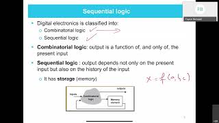
Combinational circuits are fundamental components in digital design, characterized by outputs determined solely by current inputs without any memory elements. VHDL (VHSIC Hardware Description Language) is a powerful tool used for describing the behavior and structure of these circuits. This section elaborates on basic examples, starting with the 2-input AND gate, showcasing the entity declaration and architectural definition. The example highlights how inputs A and B drive the output Y through a straightforward AND operation.
Following this, we delve into a more complex construction: a 4-bit full adder. This implementation requires a more intricate structure that handles multiple inputs and provides a sum and carry-out signal. Students will learn how to declare a 4-bit input entity, design the architecture that processes the sums and carries from one bit to the next, and observe how this complexity is handled within VHDL.
Through these examples, the section emphasizes the importance of understanding both the syntax and semantics of VHDL to effectively design and represent combinational circuits.
Youtube Videos


Audio Book
Dive deep into the subject with an immersive audiobook experience.
Entity Declaration for 2-input AND Gate
Chapter 1 of 2
🔒 Unlock Audio Chapter
Sign up and enroll to access the full audio experience
Chapter Content
-- Entity Declaration for 2-input AND gate
entity and_gate is
port (
A : in std_logic;
B : in std_logic;
Y : out std_logic
);
end entity and_gate;
Detailed Explanation
In VHDL (VHSIC Hardware Description Language), an entity is a fundamental building block that describes a hardware component. In this chunk, we declare an entity called 'and_gate' which represents a simple 2-input AND gate. The entity has three ports: 'A' and 'B' are inputs of type 'std_logic', and 'Y' is an output of type 'std_logic'. This declaration sets up the interface of the AND gate, specifying what inputs it requires and what output it will generate.
Examples & Analogies
Think of the 'and_gate' as a light switch where two people must agree (both inputs A and B must be 'on') to make the light (output Y) turn on. Just like you need cooperation to turn on the light, the AND gate operates only when both inputs are true.
Architecture Definition for AND Gate
Chapter 2 of 2
🔒 Unlock Audio Chapter
Sign up and enroll to access the full audio experience
Chapter Content
-- Architecture Definition for AND gate
architecture behavior of and_gate is
begin
Y <= A and B; -- AND operation
end architecture behavior;
Detailed Explanation
The architecture section provides the internal implementation details of the 'and_gate' entity. Here, we define the behavior of the AND gate using the 'architecture behavior'. The line 'Y <= A and B;' describes the function of the gate: it assigns the output Y the result of the logical AND operation between inputs A and B. This line of code effectively describes what happens inside the AND gate—if both A and B are true (or '1'), then Y will also be true (or '1').
Examples & Analogies
Imagine a scenario where two friends are trying to enter a club. The bouncer will only let them in if both friends show their tickets (both inputs A and B are true). If even one of them fails to show their ticket (one input is false), they cannot enter (output Y becomes false). This is how the AND gate functions—only outputting true when all conditions are met.
Key Concepts
-
VHDL: A powerful language for hardware description.
-
Entity Declaration: Defines the inputs, outputs, and functionality.
-
Architecture: The internal design that implements the functionality.
-
Logic Operations: Including AND, OR, XOR for output generation.
-
Carry Bit: Essential for multi-bit binary addition.
Examples & Applications
The 2-input AND gate where Y = A and B demonstrates simple output generation.
The design of a 4-bit full adder allows for adding two 4-bit binary numbers with a carry input and output.
Memory Aids
Interactive tools to help you remember key concepts
Rhymes
For an AND gate, both must agree, Y is true, but only if A and B.
Stories
Imagine two friends holding hands; only when both are connected do they glow together, just like an AND gate.
Memory Tools
A circuit's output: Always Ands, True when both stand.
Acronyms
AND = Both A and B are required for a true output.
Flash Cards
Glossary
- VHDL
VHSIC Hardware Description Language used to describe the behavior and structure of electronic systems.
- Entity Declaration
A VHDL block that defines the external interface of a circuit, including its inputs and outputs.
- Architecture
The VHDL construct that defines the internal behavior of an entity.
- std_logic
A data type in VHDL representing a single logic value, allowing multiple states in addition to binary.
- xor
Exclusive OR operation that outputs true when the number of true inputs is odd.
- Carry
A value that can be carried over from one digit or bit to the next in binary addition.
Reference links
Supplementary resources to enhance your learning experience.