
Design of Sequential Circuits using Verilog
Interactive Audio Lesson
Listen to a student-teacher conversation explaining the topic in a relatable way.
Introduction to D Flip-Flops
🔒 Unlock Audio Lesson
Sign up and enroll to listen to this audio lesson

Today we are going to dive into D flip-flops, a key building block in sequential circuits. These circuits react to inputs while also remembering past states.

Why are flip-flops so important in digital electronics?
Great question! D flip-flops allow us to store one bit of data and change its state only at specific moments, usually on clock edges.

So, they help in creating memory units?
Exactly! They are utilized in registers, counters, and more. Let’s remember D flip-flops with the mnemonic 'D for Data'.

Could you explain how the clock signal affects the flip-flop?
Sure! The flip-flop only changes its output on the rising edge of the clock signal. This synchronization is what makes all sequential circuits function correctly.

Can we see an example of a D flip-flop implementation in Verilog?
Absolutely! Let’s check out some Verilog code that implements a D flip-flop.
Verilog Code for D Flip-Flop
🔒 Unlock Audio Lesson
Sign up and enroll to listen to this audio lesson

Here’s how we declare a D flip-flop in Verilog. The module includes inputs for data and clock, as well as outputs for the data and its complement.
What does the 'posedge CLK' mean in the code?
Good catch! 'posedge CLK' means the code inside this block executes only when the clock signal rises, ensuring accurate data capture.
What happens if the clock signal doesn't rise?
If the clock signal is low, the flip-flop maintains its previous state. That’s why D flip-flops are said to have memory!
Can you show us what the complete code looks like?
Sure! The code looks like this: `module d_flip_flop(input D, input CLK, output Q, output Q_n); always @(posedge CLK) { Q <= D; Q_n <= ~D; } endmodule`.
That looks straightforward! What’s the importance of Q_n?
Q_n provides the complementary output, which serves crucial roles in creating more complex circuits.
Applications of D Flip-Flops
🔒 Unlock Audio Lesson
Sign up and enroll to listen to this audio lesson
Now that we’ve covered the basics, let’s talk about some applications. D flip-flops are used in counters, shift registers, and more.
How do they work in counters?
In counters, flip-flops toggle their state based on the clock, allowing for counting logic by using combinations of flip-flops.
What about shift registers?
Great question! Shift registers use a series of D flip-flops to shift data bits in a specified direction on each clock pulse.
So they can transfer data as well as store it?
Absolutely! This dual functionality is what makes them extremely valuable in asynchronous systems.
Is the D flip-flop versatile in other sequential logic applications?
Definitely! D flip-flops serve as the basis for creating state machines and various forms of sequential logic circuits.
Introduction & Overview
Read summaries of the section's main ideas at different levels of detail.
Quick Overview
Standard
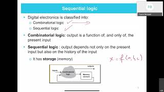
Sequential circuits are essential for storing state and memory functionality in digital systems. This section specifically highlights the design of a synchronous D flip-flop using Verilog, providing both example code and explanations of its operations in response to clock inputs.
Detailed
Design of Sequential Circuits using Verilog
In digital electronics, sequential circuits are key components that have memory elements, enabling them to store information based on both current inputs and past states. A common example of such a circuit is the D flip-flop, which utilizes a clock signal to determine when to store the input data. This section presents the design of a synchronous D flip-flop using Verilog, offering a practical implementation alongside theoretical principles. The Verilog code is structured to demonstrate how the D flip-flop captures input on the rising edge of the clock signal, thus showcasing the essence of sequential logic in practical applications. The ability to model memory and state makes these circuits indispensable in larger digital systems.
Youtube Videos


Audio Book
Dive deep into the subject with an immersive audiobook experience.
Module Declaration of D Flip-Flop
Chapter 1 of 2
🔒 Unlock Audio Chapter
Sign up and enroll to access the full audio experience
Chapter Content
module d_flip_flop(
input D, // Data input
input CLK, // Clock input
output Q, // Output Q
output Q_n // Complement of Q
);
Detailed Explanation
In Verilog, a module is a fundamental building block used to create hardware descriptions. Here, we define a module named d_flip_flop. Inside this module, we declare inputs for data (D) and clock (CLK), and outputs for the main output (Q) and its complement (Q_n), establishing a basic structure for our D flip-flop.
Examples & Analogies
Think of this module as a recipe card that lists the ingredients (inputs) and the dishes (outputs) you will make. Just like you can modify a recipe to change the dish, in hardware, this module can be reused and modified to create different circuits.
Behavior of D Flip-Flop
Chapter 2 of 2
🔒 Unlock Audio Chapter
Sign up and enroll to access the full audio experience
Chapter Content
always @(posedge CLK) begin
Q <= D; // On the rising edge of CLK, Q takes the value of D
Q_n <= ~D; // Complement of D
end
endmodule
Detailed Explanation
This block describes the functionality of the D flip-flop. The always block is triggered when there is a rising edge on the clock signal (CLK). When this edge occurs, the data from the D input is transferred to the output Q, effectively capturing the value of D at that moment. Additionally, Q_n is assigned the negation (complement) of D, providing the opposite value of Q.
Examples & Analogies
Imagine a snapshot taken by a camera. When the shutter (CLK) clicks, it captures the current scene (the value of D) and stores it as an image (the value of Q). The camera also notes the opposite colors in a negative (the complement value Q_n), which helps in editing later.
Key Concepts
-
D Flip-Flop: A storage element in sequential circuits that updates its output on the clock signal's rising edge.
-
Clock Signal: The pulse that synchronizes state changes in sequential circuits.
-
Synchronous Design: Circuit design that relies on clock signals for state updates.
Examples & Applications
Verilog implementation of a D flip-flop captures input D at the clock's rising edge, updating the output Q accordingly.
Complements the input with the output Q_n, providing a useful feature in more complex digital designs.
Memory Aids
Interactive tools to help you remember key concepts
Rhymes
In the clock's bright pour, D stores the score.
Stories
Imagine a librarian (the D flip-flop) who only updates the catalog (output Q) every time a new book (data D) arrives, but only when the bell (clock edge) rings.
Memory Tools
Remember: D stands for Data. Flip-flops flip when the clock ticks!
Acronyms
D for Data, C for Clock - Together they flip the clock rock!
Flash Cards
Glossary
- D FlipFlop
A type of flip-flop that captures the value of the input D on the rising edge of the clock signal.
- Clock Signal
A synchronization signal used in digital circuits that determines when changes in state occur.
- Synchronous Circuit
A circuit in which operations are coordinated by a clock signal, allowing for predictable state changes.
- Verilog
A hardware description language used to model electronic systems.
Reference links
Supplementary resources to enhance your learning experience.