
Combinational Circuit Design
Interactive Audio Lesson
Listen to a student-teacher conversation explaining the topic in a relatable way.
Understanding Combinational Circuits
🔒 Unlock Audio Lesson
Sign up and enroll to listen to this audio lesson

Today, we're exploring combinational circuits. Can anyone tell me how these circuits differ from sequential circuits?

I think combinational circuits only use current inputs to determine the output.
Exactly! Combinational circuits generate outputs solely based on the present inputs without using memory. Remember the phrase 'CURRENT ONLY' as a mnemonic.

What are some examples of combinational circuits?
Great question! Examples include adders, multiplexers, and logic gates like AND and OR.

How do adders fit into this?
Adders perform arithmetic operations, and we will explore how to design a 4-bit adder later on.
So to recap, combinational circuits depend on current inputs and examples include adders, multiplexers, and logic gates.
Designing Circuits in VHDL
🔒 Unlock Audio Lesson
Sign up and enroll to listen to this audio lesson

Now, let's dive into designing a 2-input AND gate using VHDL. Does anyone know what an entity declaration consists of?

It defines the inputs and outputs, right?
Correct! Here's a simple example of the entity declaration for our AND gate. Remember, it goes as follows: `entity and_gate is port ( A : in std_logic; B : in std_logic; Y : out std_logic );`.
What does the 'std_logic' mean?
Good question! `std_logic` is a data type that represents a single logic value—this will help prevent ambiguous states.
Now, let's summarize: we declared the inputs A and B, and an output Y in our AND gate entity.
Designing Circuits in Verilog
🔒 Unlock Audio Lesson
Sign up and enroll to listen to this audio lesson
Next, we will design the same 2-input AND gate but this time in Verilog. Can someone remind me what the basic component structure looks like?
It starts with the module declaration, right?
Exactly! The module for our AND gate would look like this: `module and_gate(input A, input B, output Y); assign Y = A & B;`. Notice how we use `&` instead of 'and'.
So it's simpler in some ways?
Yes, Verilog syntax can often be more succinct compared to VHDL. Let’s summarize: we learned the module declaration includes input definitions and logical assignments in Verilog.
Designing a 4-bit Adder in VHDL
🔒 Unlock Audio Lesson
Sign up and enroll to listen to this audio lesson
Now let’s tackle a more complex example—a 4-bit adder in VHDL. Who can summarize what we will include in this design?
We'll need inputs for each bit, carry-in and the outputs for sum and carry-out.
Right! We will declare four inputs for A and B, a carry-in, and outputs to represent the sum and carry out. For instance, the entity declaration will look like this: `entity full_adder_4bit is port ( A : in std_logic_vector(3 downto 0); B : in std_logic_vector(3 downto 0); Cin : in std_logic; Sum : out std_logic_vector(3 downto 0); Cout : out std_logic );`.
How does it handle the addition logic?
It's composed of XOR and AND gates with carry propagation. As a final thought, designing a 4-bit adder utilizes multiple logic levels to manage binary addition sustainably.
Introduction & Overview
Read summaries of the section's main ideas at different levels of detail.
Quick Overview
Standard
Combinational circuits are essential digital components whose outputs depend solely on current inputs. This section provides an in-depth exploration of combinational circuit design, highlighting key examples and demonstrating the design process using VHDL and Verilog coding techniques.
Detailed
Combinational Circuit Design
Combinational circuits form the backbone of digital systems by generating outputs based on only the present input values, without any memory elements influencing those outputs. In this section, we cover the essential concepts relating to the design of these circuits in both VHDL and Verilog.
Understanding Combinational Circuits
Combinational circuits utilize Boolean operations to create outputs that respond instantly to changes in input. They can be represented through various forms such as truth tables, Boolean equations, or logic diagrams. Key examples of combinational circuits include:
- Adders (like half adders and full adders)
- Multiplexers (MUX)
- Decoders
- Encoders
- Comparators
- Logic Gates (AND, OR, NOT, XOR)
Designing Combinational Circuits using VHDL
The section goes on to provide a concrete example of designing a 2-input AND gate in VHDL, illustrating the entity and architecture definitions that specify inputs, outputs, and logical operations.
Designing Combinational Circuits using Verilog
Similar to VHDL, the design of a 2-input AND gate is also demonstrated using Verilog, showing the syntax differences between the two languages.
Designing a 4-bit Adder in VHDL
A more complex example provided includes the design of a 4-bit full adder in VHDL. This involves multiple input bits and the carry-in/out function, following a logical flow for binary addition.
This section emphasizes the significance of combinational circuits in digital design, serving as the fundamental building blocks for more complex sequential circuits and their appropriate implementation using modern hardware description languages.
Youtube Videos


Audio Book
Dive deep into the subject with an immersive audiobook experience.
Understanding Combinational Circuits
Chapter 1 of 5
🔒 Unlock Audio Chapter
Sign up and enroll to access the full audio experience
Chapter Content
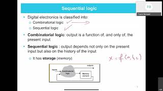
Combinational circuits are circuits where the output is purely a function of the present input.
The output is determined by applying Boolean operations to the inputs. These circuits do not have memory or storage capabilities and respond instantly to changes in input.
Detailed Explanation
Combinational circuits are defined by their behavior where the output depends only on the current inputs. Unlike sequential circuits, they lack memory elements, which means they can't store information from previous states. For example, if you change the input of a combinational circuit, the output changes immediately. The output is determined through Boolean operations such as AND, OR, and NOT applied to these inputs.
Examples & Analogies
Think of a light switch as a combinational circuit. When you flip the switch (input), the light turns on or off (output) immediately, without any delay or memory of previous states.
Basic Examples of Combinational Circuits
Chapter 2 of 5
🔒 Unlock Audio Chapter
Sign up and enroll to access the full audio experience
Chapter Content
Basic Examples of Combinational Circuits:
● Adders (e.g., half adder, full adder)
● Multiplexers (MUX)
● Decoders
● Encoders
● Comparators
● Logic Gates (AND, OR, NOT, XOR)
Detailed Explanation
Combinational circuits include several types of basic components like adders, multiplexers, decoders, and various logic gates. An adder, for instance, takes two binary numbers as inputs and produces their sum as an output. A multiplexer can select one of several inputs and forward it to the output based on a selection line. Logic gates perform fundamental operations like AND, OR, NOT, and XOR which are the building blocks for all digital circuits.
Examples & Analogies
You can liken a multiplexer to a traffic light controller that decides which road to let cars pass based on signals (the selection inputs). Just as drivers are directed based on traffic light colors, the multiplexer enables only one input at a time to flow to the output.
Design of Combinational Circuits using VHDL
Chapter 3 of 5
🔒 Unlock Audio Chapter
Sign up and enroll to access the full audio experience
Chapter Content
Example: 2-input AND Gate
-- Entity Declaration for 2-input AND gate
entity and_gate is
port (
A : in std_logic;
B : in std_logic;
Y : out std_logic
);
end entity and_gate;
-- Architecture Definition for AND gate
architecture behavior of and_gate is
begin
Y <= A and B; -- AND operation
end architecture behavior;
Detailed Explanation
This is an implementation of a 2-input AND gate using VHDL, which is a hardware description language. The entity declaration defines the AND gate with two inputs (A and B) and one output (Y). The architecture section describes the behavior of the gate, where the output Y is high only if both inputs A and B are high, implementing the AND logical operation.
Examples & Analogies
Consider the AND gate like a light switch that requires two keys (inputs). The lights (output) will only turn on if both keys are inserted (both inputs are high). If even one key is missing, the lights remain off.
Design of Combinational Circuits using Verilog
Chapter 4 of 5
🔒 Unlock Audio Chapter
Sign up and enroll to access the full audio experience
Chapter Content
Example: 2-input AND Gate
module and_gate(
input A, // Input A
input B, // Input B
output Y // Output Y
);
assign Y = A & B; // AND operation
endmodule
Detailed Explanation
This example illustrates the design of a 2-input AND gate using Verilog, another popular hardware description language. The module starts with defining the inputs A and B, and the output Y. The 'assign' statement is used to link the output Y to the result of the AND operation applied to the inputs A and B. Essentially, it implements the same logic as in the VHDL example.
Examples & Analogies
Metaphorically, this AND gate could be seen as a gate that opens only when two distinct events happen: like a door that opens only when both a password and a fingerprint are verified.
Designing a 4-bit Adder in VHDL
Chapter 5 of 5
🔒 Unlock Audio Chapter
Sign up and enroll to access the full audio experience
Chapter Content
-- Entity Declaration for 4-bit Full Adder
entity full_adder_4bit is
port (
A : in std_logic_vector(3 downto 0); -- 4-bit input A
B : in std_logic_vector(3 downto 0); -- 4-bit input B
Cin : in std_logic; -- Carry-in
Sum : out std_logic_vector(3 downto 0); -- 4-bit sum output
Cout : out std_logic -- Carry-out
);
end entity full_adder_4bit;
-- Architecture Definition for Full Adder
architecture behavior of full_adder_4bit is
signal carry : std_logic_vector(3 downto 0);
begin
-- Full Adder Logic
Sum(0) <= A(0) xor B(0) xor Cin;
carry(0) <= (A(0) and B(0)) or (Cin and (A(0) xor B(0)));
Sum(1) <= A(1) xor B(1) xor carry(0);
carry(1) <= (A(1) and B(1)) or (carry(0) and (A(1) xor B(1)));
Sum(2) <= A(2) xor B(2) xor carry(1);
carry(2) <= (A(2) and B(2)) or (carry(1) and (A(2) xor B(2)));
Sum(3) <= A(3) xor B(3) xor carry(2);
Cout <= (A(3) and B(3)) or (carry(2) and (A(3) xor B(3)));
end architecture behavior;
Detailed Explanation
In this section, we are designing a 4-bit full adder, which adds two 4-bit binary numbers and a carry-in bit. The entity declaration defines the inputs A and B as 4-bit vectors along with a carry-in (Cin), and outputs the sum (Sum) and carry-out (Cout). The architecture detail shows how the logic is implemented using XOR and AND operations to calculate each bit of the sum and manage the carry for the next bit.
Examples & Analogies
Consider a 4-bit adder like a multi-button calculator where you can add two four-digit numbers together. Each digit works independently, and any leftover value from a digit (like what you carry over in regular addition) is passed to the next digit's calculation.
Key Concepts
-
Combinational Circuits: Circuits whose outputs depend only on the current inputs.
-
Boolean Operations: The mathematical operations applied to the inputs to determine outputs.
-
VHDL and Verilog: Two languages used for designing digital circuits, each with unique syntax.
-
Entity Declaration: Defines the inputs and outputs in VHDL.
-
Module Definition: Defines the structure in Verilog.
Examples & Applications
2-input AND Gate in VHDL: An example showcasing the entity and architecture definition.
4-bit Adder: A more complex design illustrating how to handle multiple input bits and carry operation in VHDL.
Memory Aids
Interactive tools to help you remember key concepts
Rhymes
Combinational circuits in a flash, / Outputs depend on input's dash!
Stories
Imagine a magician only performing tricks based on what he sees right now; that's how combinational circuits work—no memory of past shows!
Memory Tools
Acronym M.E.L.E.: M for Memory-less, E for Either current inputs, L for Logic operations, E for Examples like adders.
Acronyms
C.I. for Combinational Inputs
Just remember C.I. for circuits that only use current inputs.
Flash Cards
Glossary
- Combinational Circuit
A type of digital circuit where the output is solely determined by the current inputs.
- VHDL
A hardware description language used for describing the behavior and structure of electronic systems.
- Verilog
A hardware description language widely used to model electronic systems.
- Entity Declaration
In VHDL, a specification that defines the interface of a module including its inputs and outputs.
- Module
In Verilog, a basic building block for design, defining inputs and outputs.
- std_logic
A data type commonly used in VHDL to represent a single binary value.
- Full Adder
A combinational circuit that adds two binary digits and accounts for a carry input.
Reference links
Supplementary resources to enhance your learning experience.