
Design of Sequential Circuits using VHDL
Interactive Audio Lesson
Listen to a student-teacher conversation explaining the topic in a relatable way.
Introduction to Sequential Circuits
🔒 Unlock Audio Lesson
Sign up and enroll to listen to this audio lesson

Today, we will delve into sequential circuits in VHDL. Can anyone tell me how sequential circuits differ from combinational circuits?

I think sequential circuits depend on past states, right?
Exactly, Student_1! Sequential circuits have memory and depend on both current inputs and previous states. Remember, 'Sequential means Storing.' That's a nice way to recall their functionality.

So, do sequential circuits include flip-flops?
Yes, they do! Flip-flops are a key example of sequential circuits. They store a bit of data based on input and clock timing.
D Flip-Flop Design in VHDL
🔒 Unlock Audio Lesson
Sign up and enroll to listen to this audio lesson

Let's look at the D flip-flop. Who can describe its function?

It holds the value of D at the clock's rising edge.
Great job, Student_3! In VHDL, we define it using an entity. Here's the code. Notice how we declare inputs and outputs clearly.

What happens if the clock isn't in a rising edge, though?
Excellent question! If there's no rising edge, the output remains unchanged. Remember, the clock controls when we sample our input.
4-bit Counter Design
🔒 Unlock Audio Lesson
Sign up and enroll to listen to this audio lesson
Now, let's implement a 4-bit counter in VHDL. Who can remind us how a counter functions?
It increments the value on each clock pulse, right?
Right! In VHDL, we also must manage reset conditions. Here’s how we declare the counter entity.
What does the reset signal do?
The reset signal sets the counter back to zero. It’s crucial for initializing your circuit. Let's remember 'Reset & Restart' when we talk counters.
Introduction & Overview
Read summaries of the section's main ideas at different levels of detail.
Quick Overview
Standard
In this section, we explore the design principles for sequential circuits utilizing VHDL. Key examples include the D flip-flop and 4-bit counter, highlighting how these circuits utilize past states alongside current inputs in digital systems.
Detailed
Design of Sequential Circuits using VHDL
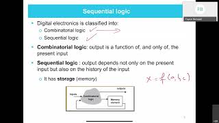
This section delves into the design of sequential circuits, emphasizing the importance of memory in digital design. Unlike combinational circuits, which rely solely on current input states, sequential circuits such as flip-flops, counters, and finite state machines depend on both current inputs and past states to function.
Key Components
- D Flip-Flop (Synchronous): A D flip-flop is a fundamental building block in sequential logic, which captures the value of the D input at a specific moment, dictated by the clock signal. In this section, we present the VHDL code for a synchronous D flip-flop. The code illustrates how to declare the entity and define the architecture, including how to handle the clock edge.
- 4-bit Counter: This example illustrates a basic 4-bit counter implemented in VHDL, showcasing how to utilize signaling for reset and clock inputs. The architecture uses a simple process to increment the count and manage resets, providing a practical example of sequential design.
Through these examples, the section aims to solidify the understanding of VHDL syntax while emphasizing the utility and application of sequential circuits in digital systems.
Youtube Videos


Audio Book
Dive deep into the subject with an immersive audiobook experience.
Entity Declaration for D Flip-Flop
Chapter 1 of 2
🔒 Unlock Audio Chapter
Sign up and enroll to access the full audio experience
Chapter Content
-- Entity Declaration for D Flip-Flop
entity d_flip_flop is
port (
D : in std_logic; -- Data input
CLK : in std_logic; -- Clock input
Q : out std_logic; -- Output Q
Q_n : out std_logic -- Complement of Q
);
end entity d_flip_flop;
Detailed Explanation
This chunk describes the entity declaration for a D Flip-Flop in VHDL. The entity keyword is used to define a module, which in this case is named d_flip_flop. Within the port section, we define the inputs and outputs of the Flip-Flop:
- D is the data input, which is of type std_logic and will hold the value to be stored.
- CLK is the clock input, which controls when the stored value updates.
- Q is the primary output of the Flip-Flop, which will show the value of D when triggered by the clock.
- Q_n is the complement of Q, showing the inverted value of the stored data.
Examples & Analogies
Think of the D Flip-Flop as a simple filing cabinet where D is the document you're currently filling out, CLK is the drawer handle you pull to lock in the document, Q is the document safely stored in the cabinet, and Q_n is the copy of the document, but with all the ink colors switched around. When you pull the drawer (the clock), whatever document (data) you had out gets stored in the cabinet (output).
Architecture Definition for D Flip-Flop
Chapter 2 of 2
🔒 Unlock Audio Chapter
Sign up and enroll to access the full audio experience
Chapter Content
-- Architecture Definition for D Flip-Flop
architecture behavior of d_flip_flop is
begin
process (CLK)
begin
if rising_edge(CLK) then
Q <= D; -- On the rising edge of CLK, Q takes the value of D
Q_n <= not D; -- Complement of D
end if;
end process;
end architecture behavior;
Detailed Explanation
This chunk outlines the architecture of the D Flip-Flop, which specifies how the Flip-Flop behaves during operation. It introduces a process that is sensitive to changes in the CLK signal. The key elements are:
- The if rising_edge(CLK) statement: This triggers when the clock signal goes from low to high (the rising edge).
- Inside this block, the output Q is assigned the value from the data input D. This means when the clock triggers, whatever value is in D gets passed to Q, thus storing it.
- Simultaneously, Q_n, the complement of D, gets updated to reflect the inverted value of D at the same clock trigger. This simultaneously provides an output that is always the opposite of Q.
Examples & Analogies
Imagine you have a light switch in your house where turning the switch on (rising edge of the clock) instantly turns on a light (output Q). The switch has a helper indicator (complement output Q_n) that turns off when the light is on. Whenever you flick that switch (the clock), the state of the light and the indicator are updated simultaneously, clearly showing what’s happening.
Key Concepts
-
Memory Elements: Sequential circuits include memory elements like flip-flops enabling them to store state information.
-
D Flip-Flop: This circuit captures data on the rising edge of a clock signal, making it crucial for timing in digital designs.
-
Clock Signal: The clock signal dictates when state changes occur, ensuring synchronization in sequential circuits.
Examples & Applications
D Flip-Flop example in VHDL demonstrating entity declaration and architecture definition.
4-bit counter shown in VHDL, illustrating how to handle incrementing and resetting based on clock and reset inputs.
Memory Aids
Interactive tools to help you remember key concepts
Rhymes
In a flip-flop, we love the clock, it tells us when to rock!
Stories
Imagine a clock meeting a flip-flop at a dance; they only change moves when the clock strikes.
Memory Tools
D for Data captures at the clock's rising edge: D = Dynamic storage.
Acronyms
F.A.C.E
Flip-flop Acounts Clock Events.
Flash Cards
Glossary
- D FlipFlop
A memory element that captures the value of the data input on the rising edge of the clock signal.
- Sequential Circuit
A type of digital circuit where the output depends on current inputs and past states.
- VHDL
VHSIC Hardware Description Language, a programming language used to model electronic systems.
- 4bit Counter
A sequential circuit that maintains a count in binary format, capable of counting from 0 to 15.
Reference links
Supplementary resources to enhance your learning experience.