
Design of a 4-bit Counter in VHDL
Interactive Audio Lesson
Listen to a student-teacher conversation explaining the topic in a relatable way.
Introduction to 4-bit Counter Design
🔒 Unlock Audio Lesson
Sign up and enroll to listen to this audio lesson

Today, we are looking into designing a 4-bit counter using VHDL. Can anyone tell me what a counter does in digital systems?

A counter keeps track of the number of occurrences of an event?
That's right! A counter is crucial for counting events, like pulses from a clock. Now, let's talk about the 4-bit designation. What does that mean?

It means the counter can count from 0 to 15, since 2 to the power of 4 is 16.
Exactly! Great job! Now, let's get into the details. What inputs do you think we need for our counter?

We need a clock input to keep track of time, and a reset input to set the counter back to zero.
Correct! The clock initiates the counting, while the reset allows us to set the count to zero.
Entity Declaration in VHDL
🔒 Unlock Audio Lesson
Sign up and enroll to listen to this audio lesson

Let’s look at how we declare our entity in VHDL for the 4-bit counter. Can anyone tell me the syntax we would use?

We start with `entity counter_4bit is` followed by the port declaration.
Exactly! We need to define our ports carefully. What ports do we specify?
We would use `CLK` for clock input, `RESET` for the reset input, and `Q` for the output count.
Good! Now remember, the output `Q` should be a vector since it's a 4-bit counter.
Architecture Definition of the Counter
🔒 Unlock Audio Lesson
Sign up and enroll to listen to this audio lesson
Moving on to the architecture! Can anyone explain how we can implement the counting logic?
We need to create a process that checks for the `CLK` and `RESET` signals.
Correct! In that process, what's our first condition?
If `RESET` is '1', we set our count to zero.
Exactly! And what happens on a rising edge of `CLK`?
We increment the count by 1!
Well done! Let’s wrap it up by discussing how we assign the current count to output.
Summary and Real-World Application
🔒 Unlock Audio Lesson
Sign up and enroll to listen to this audio lesson
To conclude, we’ve designed a 4-bit counter in VHDL. Why is this design important?
It’s used in many applications, including timers and frequency dividers!
Exactly! Counters like this are foundational to digital systems. What would be a real-world scenario using this counter?
A digital clock that counts seconds.
Perfect example! They help keep track of time! Now, any final questions?
Introduction & Overview
Read summaries of the section's main ideas at different levels of detail.
Quick Overview
Standard
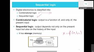
In this section, we explore how to design a 4-bit counter in VHDL. The focus is on defining the entity with inputs for clock and reset signals, and an output for the count. The architecture includes a process that manages the counting logic, resetting, and state transitions.
Detailed
Design of a 4-bit Counter in VHDL
The design of a 4-bit counter in VHDL involves creating an entity that has inputs for a clock signal and a reset signal, and an output that is a 4-bit vector representing the current count.
Entity Declaration:
The entity declaration specifies the inputs and outputs. Here, we define the count register to hold the current count state. The RESET signal is used to reset the count to zero, while the CLK signal allows the counter to increment on each clock pulse.
Architecture Definition:
Inside the architecture, a process is defined that monitors the CLK and RESET signals. If the RESET signal is activated (set to '1'), the counter resets. If a rising edge of CLK is detected, the counter increments its count by one. Finally, the current count is assigned to the output.
This section exemplifies how VHDL can be utilized for sequential circuit design, specifically for counters, reinforcing the understanding of state-based outputs.
Youtube Videos


Audio Book
Dive deep into the subject with an immersive audiobook experience.
Entity Declaration for 4-bit Counter
Chapter 1 of 2
🔒 Unlock Audio Chapter
Sign up and enroll to access the full audio experience
Chapter Content
-- Entity Declaration for 4-bit Counter
entity counter_4bit is
port (
CLK : in std_logic; -- Clock input
RESET : in std_logic; -- Reset input
Q : out std_logic_vector(3 downto 0) -- 4-bit output
);
end entity counter_4bit;
Detailed Explanation
In this chunk, we define the entity for a 4-bit counter in VHDL. The 'entity' keyword begins the declaration of a new hardware component. The 'counter_4bit' is the name of the entity, and it includes a set of ports: CLK (the clock input), RESET (the reset input), and Q (the output which is a 4-bit vector). This structure allows the counter to receive inputs and produce outputs.
Examples & Analogies
Think of the entity declaration like designing a new appliance, say a microwave oven. You label the microwave (entity), and specify its buttons for power (CLK), a reset button (RESET), and the display (Q) showing the cooking time in hours and minutes (4-bit output).
Architecture Definition for 4-bit Counter
Chapter 2 of 2
🔒 Unlock Audio Chapter
Sign up and enroll to access the full audio experience
Chapter Content
-- Architecture Definition for 4-bit Counter
architecture behavior of counter_4bit is
signal count : std_logic_vector(3 downto 0) := "0000"; -- 4-bit count register
begin
process (CLK, RESET)
begin
if RESET = '1' then
count <= "0000"; -- Reset the counter to 0
elsif rising_edge(CLK) then
count <= count + 1; -- Increment the counter on each clock pulse
end if;
end process;
Q <= count; -- Output the current count value
end architecture behavior;
Detailed Explanation
This chunk describes the 'architecture' of the 4-bit counter which defines how it behaves. Inside this architecture, we declare a signal 'count' that acts as a 4-bit register starting at '0000'. A process block watches for changes in CLK and RESET. If RESET is activated, 'count' is set back to '0000'. If a rising edge of CLK is detected, the counter increments its value by one. Finally, the output Q is assigned the current count value.
Examples & Analogies
Imagine a digital clock that resets to zero when you press a reset button (RESET). Every tick of the clock (CLK) represents a second passing when the clock counts from '0000' to '0001', then to '0002', and so on, just like how the counter increases its value with each clock pulse.
Key Concepts
-
Entity Declaration: The definition of inputs and outputs for a VHDL design.
-
Architecture: The description of how an entity behaves.
-
4-bit Counter Operation: The counter counts from 0 to 15 in binary.
-
Reset Functionality: Resets the counter's value to 0 when activated.
-
Clock Incrementing: The process of increasing the count with each clock pulse.
Examples & Applications
The counter increments from 0000 to 0001, then to 0010, and continues until it reaches 1111 before cycling back to 0000.
Using a 4-bit counter in a digital timer that counts upward every second.
Memory Aids
Interactive tools to help you remember key concepts
Rhymes
Count to four, and don’t forget, on RESET you start again, that’s the bet!
Acronyms
C-R-Q
Count
Reset
and Query your output - make sure to remember!
Stories
Imagine a clock tower that chimes every hour. It uses a 4-bit counter to keep track of the hours from 0 to 15 but resets back to 0 when the clock strikes 12.
Memory Tools
To remember the steps: Reset (to 0), Count (up), and CLK (ticks to increment).
Flash Cards
Glossary
- 4bit Counter
A digital counter that can represent values from 0 to 15 using four bits.
- Entity
Defines an object in VHDL describing its inputs and outputs.
- Architecture
The internal structure and behavior of an entity in VHDL.
- RESET
A signal that initializes the counter to a starting state, typically zero.
- CLK
The clock signal that synchronizes events in sequential logic circuits.
Reference links
Supplementary resources to enhance your learning experience.