
Design of a 4-bit Counter in Verilog
Interactive Audio Lesson
Listen to a student-teacher conversation explaining the topic in a relatable way.
Understanding a 4-bit Counter
🔒 Unlock Audio Lesson
Sign up and enroll to listen to this audio lesson

Today, we will learn about a 4-bit counter in Verilog. Can anyone explain what a counter is?

A counter keeps track of the number of occurrences of an event, right?
Exactly! And what about a 4-bit counter? How does its limitation help in design?

A 4-bit counter can count from 0 to 15 because it uses 4 bits, which means it can represent 16 values.
Great! So, understanding the range is crucial. We will explore how to implement this in Verilog now.
Verilog Structure for a 4-bit Counter
🔒 Unlock Audio Lesson
Sign up and enroll to listen to this audio lesson

Let's look at the Verilog code structure for our counter. What do you think the purpose of the `input` and `output` keywords is?

They define what signals go into the module and what it outputs.
Correct! Now let's discuss the `reg` type for `count`. Why do we use it here?

A `reg` type is used for variables that get updated in procedural blocks like `always`.
Yes! The `always` block is crucial for defining how our counter behaves with clock edges. Moving on, we'll simplify how these components interact.
Logic for Incrementing the Count
🔒 Unlock Audio Lesson
Sign up and enroll to listen to this audio lesson
When does our counter reset, according to the Verilog code?
It resets to 0 if the `RESET` input is high.
Correct! How about when does it increment?
It increments on every rising edge of `CLK`, as long as `RESET` is not active.
Good observations! This systematic checking is essential, ensuring the counter behaves correctly.
Output Assignment
🔒 Unlock Audio Lesson
Sign up and enroll to listen to this audio lesson
Finally, how do we make the count available from our counter module?
We use the `assign` statement to link `Q` to `count`.
That's perfect! This is how we transfer the value from our internal representation to external usage.
So, `assign Q = count;` means Q reflects the current count value?
Exactly! Now let's wrap up with a brief overview of what we learned.
Introduction & Overview
Read summaries of the section's main ideas at different levels of detail.
Quick Overview
Standard
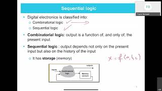
The design of a 4-bit counter in Verilog involves creating a module that includes input signals for clock and reset, a register to store the count, and logic to increment the counter on each clock pulse while being reset when necessary.
Detailed
Design of a 4-bit Counter in Verilog
In this section, we explore the implementation of a 4-bit counter using Verilog, a popular hardware description language. The primary function of a counter is to keep track of occurrences or successive events, which is pivotal in various digital systems. The counter design comprises inputs for clock (CLK) and reset (RESET), allowing the counter to reset the count to zero on a high reset signal and increment the count on each clock pulse.
The Verilog code illustrates the counter architecture, where a register count holds the current count value, defined as a 4-bit wide register. The design employs an always block triggered by the rising edge of CLK or RESET signal, thus ensuring that the counter updates correctly. The assign statement outputs the current value of the counter.
This section not only provides practical coding examples but also emphasizes the significance of counters in the realm of digital electronics, aiding in building more complex systems.
Youtube Videos


Audio Book
Dive deep into the subject with an immersive audiobook experience.
Module Declaration for the 4-bit Counter
Chapter 1 of 4
🔒 Unlock Audio Chapter
Sign up and enroll to access the full audio experience
Chapter Content
module counter_4bit(
input CLK, // Clock input
input RESET, // Reset input
output [3:0] Q // 4-bit output
);
Detailed Explanation
In this chunk, we begin by declaring the Verilog module for the 4-bit counter. The module is named counter_4bit. It has three ports: CLK, which is the clock input; RESET, which is used to reset the counter; and Q, which is a 4-bit output that will hold the current count value. The comment next to each port clarifies their purposes.
Examples & Analogies
Think of this module as a team of workers in a factory. CLK is like the rhythm of the factory's machinery that tells the workers when to perform their tasks. RESET is like a supervisor who can quickly reset all the workers back to their starting positions if there’s a mistake. Q is the final product that shows the current count, like the number of completed products on a conveyor belt.
Counter Register Declaration
Chapter 2 of 4
🔒 Unlock Audio Chapter
Sign up and enroll to access the full audio experience
Chapter Content
reg [3:0] count; // 4-bit counter register
Detailed Explanation
Here, we declare a 4-bit register named count. This register will hold the value of the count. The keyword reg indicates that this variable will hold its value even when there is no clock edge; it retains its state until explicitly changed.
Examples & Analogies
Imagine count as a scorecard in a game that keeps track of points. Even if no one is playing (no clock edge), the scorecard waits and holds the last score until someone scores again or resets the game.
Counter Logic
Chapter 3 of 4
🔒 Unlock Audio Chapter
Sign up and enroll to access the full audio experience
Chapter Content
always @(posedge CLK or posedge RESET) begin
if (RESET)
count <= 4'b0000; // Reset the counter
else
count <= count + 1; // Increment the counter
end
Detailed Explanation
This chunk contains the main logic of the counter. The always block is triggered on the positive edge of the CLK signal or when the RESET signal is activated. If RESET is high, the counter resets to 0 (binary 0000). If not, the counter increments by 1 on each clock pulse. The use of posedge ensures the counter only changes at a specific moment when the clock signal transitions from low to high.
Examples & Analogies
Consider this as a digital stopwatch. When you press the reset button (reset signal), it goes back to zero, just like setting a timer at the start of an event. Every time the clock ticks (the CLK pulse), the timer increases by one second, counting up as time passes.
Output Assignment
Chapter 4 of 4
🔒 Unlock Audio Chapter
Sign up and enroll to access the full audio experience
Chapter Content
assign Q = count; // Output the current count value
endmodule
Detailed Explanation
In this final chunk, the output Q is assigned the value of count. This means whatever value is currently held in the count register will be reflected in Q, which reflects the current state of the counter. The endmodule keyword signifies the end of the module definition.
Examples & Analogies
Think of Q as a digital display board in a scoreboard. The display board shows the current count from the scorecard (count). Whenever the score changes, it updates to reflect the new score, just like how Q shows the latest count value.
Key Concepts
-
4-bit Counter: A counter that can hold values from 0 to 15 due to its 4-bit limit.
-
Reset Functionality: The counter can be reset to zero using a
RESETsignal. -
Clock Pulses: The counter increments on the rising edge of the clock signal.
Examples & Applications
When clock pulses occur, the counter increments sequentially from 0000 (0) to 1111 (15).
If the RESET signal is activated, the counter immediately returns to 0000 regardless of its current state.
Memory Aids
Interactive tools to help you remember key concepts
Rhymes
When the clock ticks and the reset's clear, the counter adds without any fear.
Stories
Imagine a race where everyone counts their laps; our 4-bit counter is the top runner, counting from 0 to 15.
Memory Tools
C.R.C. - Count, Reset, Clock: remember, a counter counts on clock pulses and can reset anytime.
Acronyms
C.C.C. - Counter, Clock, Counted - for remembering the essence of a 4-bit counter.
Flash Cards
Glossary
- Counter
A digital circuit that counts the number of clock pulses and produces a binary output.
- Verilog
A hardware description language used to model electronic systems.
- Reset
An input signal that clears the counter back to its initial state.
- Clock Pulse
A signal used to synchronize events in digital circuits.
- Reg
A data type in Verilog used to store values in procedural blocks.
Reference links
Supplementary resources to enhance your learning experience.