
Sequential Circuit Design
Interactive Audio Lesson
Listen to a student-teacher conversation explaining the topic in a relatable way.
Understanding Sequential Circuits
🔒 Unlock Audio Lesson
Sign up and enroll to listen to this audio lesson

Today, we're diving into sequential circuits! Can anyone tell me how they differ from combinational circuits?

I think sequential circuits use memory, so their output relies on past inputs, right?
Exactly! Sequential circuits remember previous states. That's why they are crucial for tasks such as counting and tracking states.

What are some basic examples of sequential circuits?
Great question! Some examples are flip-flops, counters, and finite state machines which are all integral to designing complex digital systems.

Why is it important to understand sequential circuits?
Because they allow us to create systems that can store and retrieve information, making them essential for modern computing and electronics.
To summarize, sequential circuits have memory, rely on past states, and include components like flip-flops and counters.
Designing Sequential Circuits using VHDL
🔒 Unlock Audio Lesson
Sign up and enroll to listen to this audio lesson

Now, let's look at designing a D Flip-Flop in VHDL. Can anyone tell me the basic components of a D Flip-Flop?

It has data input, clock input, output Q, and the complement Q_n!
Exactly! The D Flip-Flop captures the value of input D at the rising edge of the clock signal. Let’s check out the VHDL code for this design.
Could you explain what the process block does in the code?
Of course! The process block is triggered at the rising edge of the CLK signal. It sets Q to D and Q_n to the complement of D. This is a core concept in sequential logic!
What if the clock signal doesn't rise?
If the clock signal remains unchanged, the output will retain its previous state, which is a key feature of sequential circuits.
To summarize, we discussed the D Flip-Flop’s components, its function in capturing input on a clock edge, and the relevance of the process block in VHDL.
Designing a 4-bit Counter in Verilog
🔒 Unlock Audio Lesson
Sign up and enroll to listen to this audio lesson
Moving on, let’s design a 4-bit counter in Verilog. What do you think are the main components of a counter?
It would need a clock input, a reset input, and an output to show the count!
Absolutely! The counter increases its value with each clock pulse. Let's look at the Verilog implementation now.
Can you explain the role of the 'always' block in this code?
Sure! The 'always' block monitors the clock signal and any reset. It will reset the count to zero when the reset signal is high or increment the count on each clock pulse. This is fundamental to sequential circuits!
What happens if the reset is not triggered?
The counter continues to increase with every clock cycle, demonstrating the memory aspect of sequential circuits.
In summary, we learned how to design a 4-bit counter in Verilog, focusing on its components and the 'always' block functionality.
Introduction & Overview
Read summaries of the section's main ideas at different levels of detail.
Quick Overview
Standard
This section introduces sequential circuits, explaining their reliance on memory elements to store information and providing examples such as flip-flops, counters, and finite state machines. It also covers design methodologies in both VHDL and Verilog for implementing these circuits.
Detailed
Sequential Circuit Design
Sequential circuits are a cornerstone in digital design that incorporate memory elements, allowing their outputs to depend not just on current inputs but also on past states. This capability makes them suitable for applications in various systems, including counters, registers, and finite state machines (FSMs).
In this section, we explore key elements of sequential circuits. We begin with a foundational understanding of sequential circuits, distinguishing them from combinational circuits, with foundational examples like flip-flops, counters, and registers. The design approaches using VHDL and Verilog are detailed, showcasing the implementation of a D Flip-Flop and a 4-bit counter in both hardware description languages. This instruction provides the groundwork for designing more complex digital systems, emphasizing the practical applications of sequential logic in modern electronic systems.
Youtube Videos


Audio Book
Dive deep into the subject with an immersive audiobook experience.
Understanding Sequential Circuits
Chapter 1 of 5
🔒 Unlock Audio Chapter
Sign up and enroll to access the full audio experience
Chapter Content
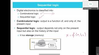
Sequential circuits have memory elements, meaning that their outputs depend on both the current inputs and the past inputs (or states). These circuits store information about previous events, which makes them suitable for applications like counters, registers, and state machines.
Basic Examples of Sequential Circuits:
● Flip-flops (D flip-flop, JK flip-flop, SR flip-flop)
● Counters (Binary counters, Decade counters)
● Registers
● Finite State Machines (FSMs)
Detailed Explanation
Sequential circuits are a type of digital circuit where the output is influenced not just by the current input, but also by the previous state or input history. This capability allows them to 'remember' information, which is crucial for many applications such as counters that keep track of numbers, registers that hold data temporarily, and finite state machines that model complex sequences of operations. The memory elements in these circuits, like flip-flops, allow for this retention of past states.
Examples & Analogies
Consider a light switch that remembers its last state. If the switch is turned on and then off, if you turn it back on, it should recall that it was on last. Similarly, a counter keeps track of how many times you have pressed the button to increment a score in a game, maintaining the tally until you reset it.
Design of Sequential Circuits using VHDL - D Flip-Flop
Chapter 2 of 5
🔒 Unlock Audio Chapter
Sign up and enroll to access the full audio experience
Chapter Content
Example: D Flip-Flop (Synchronous)
-- Entity Declaration for D Flip-Flop
entity d_flip_flop is
port (
D : in std_logic; -- Data input
CLK : in std_logic; -- Clock input
Q : out std_logic; -- Output Q
Q_n : out std_logic -- Complement of Q
);
dend entity d_flip_flop;
-- Architecture Definition for D Flip-Flop
architecture behavior of d_flip_flop is
begin
process (CLK)
begin
if rising_edge(CLK) then
Q <= D; -- On the rising edge of CLK, Q takes the value of D
Q_n <= not D; -- Complement of D
end if;
end process;
end architecture behavior;
Detailed Explanation
In VHDL, a D Flip-Flop is defined using an entity declaration and architecture definition. The entity specifies the inputs: D (data input), CLK (clock input), and the outputs: Q (the output value) and Q_n (the complement of Q). Within the architecture, a process is created that reacts to the clock signal. On the rising edge of the clock, the output Q is assigned the value of D, meaning it updates Q to match the input D at the clock's trigger. At the same time, Q_n is set to the opposite of D.
Examples & Analogies
Think of the D flip-flop as a train that only moves from one station (the output state) to another when it receives a clear signal (the clock pulse). At each station (clock pulse), the train can choose to take a passenger (the input) on board. If you think of this as a bus where, at each stop, the bus driver checks who is getting on, that’s exactly how the D flip-flop works!
Design of Sequential Circuits using Verilog - D Flip-Flop
Chapter 3 of 5
🔒 Unlock Audio Chapter
Sign up and enroll to access the full audio experience
Chapter Content
Example: D Flip-Flop (Synchronous)
module d_flip_flop(
input D, // Data input
input CLK, // Clock input
output Q, // Output Q
output Q_n // Complement of Q
);
always @(posedge CLK) begin
Q <= D; // On the rising edge of CLK, Q takes the value of D
Q_n <= ~D; // Complement of D
end
endmodule
Detailed Explanation
In Verilog, the D Flip-Flop is defined using a module which specifies its input and output ports. The flip-flop's operation is described in an always block that activates on the rising edge of the clock. During this activation, the output Q is assigned the current value of the data input D, and simultaneously, Q_n is assigned the complement of D (the opposite value). This ensures that the flip-flop consistently and accurately reflects the input data synchronized with the clock.
Examples & Analogies
Imagine a director at a film set (the clock) who gives the signal for action. The actors (data input) perform based on the scene set earlier. Only when the director says 'action' does the scene unfold, just like how the D flip-flop only changes its output when the clock triggers.
Design of a 4-bit Counter in VHDL
Chapter 4 of 5
🔒 Unlock Audio Chapter
Sign up and enroll to access the full audio experience
Chapter Content
-- Entity Declaration for 4-bit Counter
entity counter_4bit is
port (
CLK : in std_logic; -- Clock input
RESET : in std_logic; -- Reset input
Q : out std_logic_vector(3 downto 0) -- 4-bit output
);
end entity counter_4bit;
-- Architecture Definition for 4-bit Counter
architecture behavior of counter_4bit is
signal count : std_logic_vector(3 downto 0) := "0000"; -- 4-bit count register
begin
process (CLK, RESET)
begin
if RESET = '1' then
count <= "0000"; -- Reset the counter to 0
elsif rising_edge(CLK) then
count <= count + 1; -- Increment the counter on each clock pulse
end if;
end process;
Q <= count; -- Output the current count value
end architecture behavior;
Detailed Explanation
This VHDL code defines a 4-bit counter that increments its count on every clock cycle. It includes an entity declaration that specifies the counter's inputs and output. The architecture defines a signal, count, which initially holds the binary value '0000'. Within a process block that is triggered by changes to the clock or reset inputs, if the reset signal is active, the counter resets to '0000'. Otherwise, on each rising edge of the clock, the counter value increases by 1. The current count is output as Q.
Examples & Analogies
Think of the 4-bit counter as a tally counter used by a person counting the number of people entering a store. Whenever a person enters (akin to a clock pulse), they increment the tally by one. If the store needs to reset (like pressing a reset button), the counter goes back to zero, waiting to count again.
Design of a 4-bit Counter in Verilog
Chapter 5 of 5
🔒 Unlock Audio Chapter
Sign up and enroll to access the full audio experience
Chapter Content
module counter_4bit(
input CLK, // Clock input
input RESET, // Reset input
output [3:0] Q // 4-bit output
);
reg [3:0] count; // 4-bit counter register
always @(posedge CLK or posedge RESET) begin
if (RESET)
count <= 4'b0000; // Reset the counter
else
count <= count + 1; // Increment the counter
end
assign Q = count; // Output the current count value
endmodule
Detailed Explanation
The Verilog module for the 4-bit counter operates similarly to the VHDL version. It uses a register (count) to maintain the current count. An always block defines the behavior where on the rising edge of the clock or when the reset signal is activated, the counter either resets to zero or increments by one. The current count is then assigned to the output Q, making it available for other circuits or processes.
Examples & Analogies
Imagine a scoreboard at a game. Every time a goal is scored (like the clock pulse), the score increases by one point. If there's a need to reset the score (perhaps at the start of a new game), the scoreboard goes back to zero, ready to count anew. This mimics how the counter works in a digital system.
Key Concepts
-
Memory: The ability of sequential circuits to retain past states.
-
Flip-Flops: The building blocks of sequential circuits, capturing input at clock edges.
-
Counters: Sequential circuits that tally counts based on clock signals.
-
FSM: A model that describes transitions between states in a system.
Examples & Applications
A D Flip-Flop captures input D on the rising edge of a clock signal.
A 4-bit counter increments its output value with each clock cycle.
Memory Aids
Interactive tools to help you remember key concepts
Rhymes
Flip-flops flip, events they keep, counting circuits pulse and leap.
Stories
Imagine a classroom where students pass notes. Each student can only talk when the bell rings, just like a clock controlling flip-flops that remember notes (states). When it's reset, all notes go back to zero.
Memory Tools
FFor CCounting - Flip-Flops for Counting Circuits.
Acronyms
F.A.C.E.
Flip-Flop - Action - Counter - Events.
Flash Cards
Glossary
- Sequential Circuit
A circuit whose output depends on both current inputs and past states.
- FlipFlop
A memory element capable of storing one bit of data.
- Counter
A sequential circuit that counts pulses and can store its state.
- Finite State Machine (FSM)
A computational model used to design sequential logic that consists of a finite number of states.
- VHDL
A hardware description language used for modeling and designing electronic systems.
- Verilog
A hardware description language used for digital design and modeling electronic systems.
Reference links
Supplementary resources to enhance your learning experience.