
Designing a 4-bit Adder in VHDL
Interactive Audio Lesson
Listen to a student-teacher conversation explaining the topic in a relatable way.
Introduction to Full Adders
🔒 Unlock Audio Lesson
Sign up and enroll to listen to this audio lesson

Today we'll discuss the full adder. Can anyone tell me what a full adder does?

Does it add two bits together and include a carry bit?
That's correct! A full adder adds two binary digits and a carry-in to produce a sum and a carry-out. It’s a fundamental building block for larger adders.

So, how does this apply when we want to add more than one bit?
Great question! We can cascade multiple full adders to create a n-bit adder, like our 4-bit adder. Let's see how we declare this in VHDL.
VHDL Entity Declaration
🔒 Unlock Audio Lesson
Sign up and enroll to listen to this audio lesson

In VHDL, we start with the entity declaration. Can someone summarize what we need in our entity for a 4-bit adder?

We need two 4-bit inputs, a carry-in, a 4-bit output, and a carry-out.
Exactly! The entity declaration will look like this. Let's write it out.
"```vhdl
Architecture Definition
🔒 Unlock Audio Lesson
Sign up and enroll to listen to this audio lesson
Now, let's focus on the architecture. What do you think we'll need to define in here?

We need to calculate the sum and how the carry is passed from one bit to the next.
That's crucial! The carry must propagate through the bits. The architecture will also utilize signals to manage these carries. Here's how we can define that logic.
"```vhdl
Combining Logic with VHDL
🔒 Unlock Audio Lesson
Sign up and enroll to listen to this audio lesson
The logic behind our adder uses basic operations: XOR for sum and AND for carry. Can anyone explain why we use these operations?
XOR gives us the sum of inputs when there is no carry, and AND helps us determine if a carry exists!
Correct! This is what forms the backbone of binary addition. Each bit's handling is crucial for cascading adders correctly.
Review and Reflect
🔒 Unlock Audio Lesson
Sign up and enroll to listen to this audio lesson
To summarize our discussion, we explored the 4-bit full adder's design in VHDL. What are the key components we've learned today?
The entity declaration, how we structure the architecture, and utilizing logic gates for calculations!
Exactly! Keep in mind that understanding these fundamentals will pave the way for more complex circuits in digital design.
Introduction & Overview
Read summaries of the section's main ideas at different levels of detail.
Quick Overview
Standard
The development of a 4-bit full adder in VHDL is outlined, including the entity declaration and architecture definition. Key components such as carry signals and sum operations are explained to illustrate the functionality of this combinational circuit.
Detailed
Detailed Summary
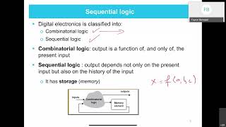
In this section, we dive into the design of a 4-bit full adder using VHDL. A full adder is a basic combinational circuit that adds binary numbers and accounts for values carried in from previous digits. The entity declaration for the 4-bit full adder specifies the inputs, including two 4-bit vectors (A and B) and a carry-in (Cin), as well as the outputs, which consist of a 4-bit sum (Sum) and a carry-out (Cout).
The architecture section outlines the internal signals and the logic for computing the sum and carrying signals through a series of XOR and AND operations. Each bit of the sum is calculated using its corresponding bits from the input vectors and the previous carry, ensuring that the adder functions correctly for both single bit and multi-bit operations. This clear structure underlines the importance of understanding signal flow and logic in hardware description languages like VHDL.
Youtube Videos


Audio Book
Dive deep into the subject with an immersive audiobook experience.
Entity Declaration for 4-bit Full Adder
Chapter 1 of 2
🔒 Unlock Audio Chapter
Sign up and enroll to access the full audio experience
Chapter Content
-- Entity Declaration for 4-bit Full Adder
entity full_adder_4bit is
port (
A : in std_logic_vector(3 downto 0); -- 4-bit input A
B : in std_logic_vector(3 downto 0); -- 4-bit input B
Cin : in std_logic; -- Carry-in
Sum : out std_logic_vector(3 downto 0); -- 4-bit sum output
Cout : out std_logic -- Carry-out
);
end entity full_adder_4bit;
Detailed Explanation
This section defines the entity 'full_adder_4bit'. In VHDL (VHSIC Hardware Description Language), an entity is a building block for digital circuits. Here, we declare this entity to handle a 4-bit full adder. The 'port' section lists the inputs and outputs:
- A and B are both 4-bit inputs, represented as 'std_logic_vector(3 downto 0)', meaning each can hold 4 bits.
- Cin is a single-bit input, indicating a carry-in bit that is used for addition.
- Sum is a 4-bit output that will store the result of the addition.
- Cout is also a single-bit output that indicates any overflow from the addition (the carry-out).
Examples & Analogies
Think of the entity here as a factory that assembles bikes. Each bike has components: the wheels (inputs A and B), a handlebar (carry-in), the assembled bike (output Sum), and an overflow area for unused parts (Cout). Each component plays a crucial role in ensuring the factory outputs a functional bike.
Architecture Definition for Full Adder
Chapter 2 of 2
🔒 Unlock Audio Chapter
Sign up and enroll to access the full audio experience
Chapter Content
-- Architecture Definition for Full Adder
architecture behavior of full_adder_4bit is
signal carry : std_logic_vector(3 downto 0);
begin
-- Full Adder Logic
Sum(0) <= A(0) xor B(0) xor Cin;
carry(0) <= (A(0) and B(0)) or (Cin and (A(0) xor B(0)));
Sum(1) <= A(1) xor B(1) xor carry(0);
carry(1) <= (A(1) and B(1)) or (carry(0) and (A(1) xor B(1)));
Sum(2) <= A(2) xor B(2) xor carry(1);
carry(2) <= (A(2) and B(2)) or (carry(1) and (A(2) xor B(2)));
Sum(3) <= A(3) xor B(3) xor carry(2);
Cout <= (A(3) and B(3)) or (carry(2) and (A(3) xor B(3)));
end architecture behavior;
Detailed Explanation
This part of the code defines the actual workings of the 4-bit full adder. In the 'architecture behavior,' we declare a signal called 'carry' to keep track of the carry bits during addition. The architecture contains several statements that implement the full adder's logic:
- The first line computes the least significant bit of the sum (Sum(0)) using the XOR operation, which effectively adds the bits from inputs A and B and considers the carry-in (Cin).
- The next line computes the carry-out for this bit position (carry(0)). It determines if there is an overflow needing to carry to the next bit position.
- The same logic is repeated for Sum(1), Sum(2), and Sum(3), ensuring that each bit is correctly calculated along with the necessary carry bits, leading to proper addition of the entire 4 bits.
- Finally, Cout is computed, which decides if there’s an overflow after calculating the most significant bit.
Examples & Analogies
Think of solving addition with multiple digits. When adding 29 and 15, you start from the rightmost digit, add 9 and 5 (you get a sum of 14, which means you write down 4 and carry over 1). Repeat the process for the next column. Each carry-over is like the carry signals in our VHDL logic, keeping track of any overflow to ensure the final answer is correct.
Key Concepts
-
Entity Declaration: Useful for defining inputs and outputs of a hardware description in VHDL.
-
Architecture: Refers to how the internals of the entity structure are described, including logic operations.
Examples & Applications
The full adder is an essential component in the design of arithmetic logic units (ALUs) used in CPUs.
Cascading multiple 4-bit adders allows for the addition of larger binary numbers.
Memory Aids
Interactive tools to help you remember key concepts
Rhymes
When adding bits with care, don't forget to share, the carry to the next, in the full adder's quest.
Stories
Imagine two friends trying to share apples. If one has 5 apples, and the other has 3, they add up their apples and share one with the next friend – even the leftover counts as a carry.
Memory Tools
Remember 'A+B+C' as the way to sum with this adder, where A and B are bits, and C is the carry.
Acronyms
Use the acronym 'CASS' - Carry And Sum Signals - to remember the full adder's key operations.
Flash Cards
Glossary
- Full Adder
A combinational circuit that outputs the sum of two binary digits and a carry-in.
- VHDL
VHSIC Hardware Description Language, used for modeling electronic systems.
- Entity Declaration
A part of VHDL code that defines the inputs and outputs of a circuit.
- Architecture
The portion of VHDL that describes the internal behavior of an entity.
- Carry
A binary value that is carried over to the next digit when adding binary numbers.
Reference links
Supplementary resources to enhance your learning experience.