
Design of an FSM for Traffic Light Controller (VHDL)
Interactive Audio Lesson
Listen to a student-teacher conversation explaining the topic in a relatable way.
Introduction to FSMs
🔒 Unlock Audio Lesson
Sign up and enroll to listen to this audio lesson

Today, we'll discuss Finite State Machines or FSMs. Can anyone tell me what an FSM is?

Isn't it a model that can be in different states at different times?
Exactly! FSMs allow us to track inputs and produce outputs based on defined states. They are fundamental in control systems. Remember, FSMs constitute a finite number of states, transitions, and outputs.

Can FSMs be used for things other than traffic lights?
Absolutely! You'll find them in everything from pedestrian crossings to digital clocks and even protocol handlers in communications.
To remember: think RYG for Red, Yellow, and Green when we talk about traffic lights.

RYG! Easy to remember!
Good! Let's dive deeper into the FSM for a traffic light controller next.
Entity Declaration and Architecture
🔒 Unlock Audio Lesson
Sign up and enroll to listen to this audio lesson

In VHDL, we need to declare our entity first. Who can tell me how we declare the traffic light FSM?
We define the entity with inputs and an output vector for the lights.
"Correct! The entity declaration specifies the input clock and reset signals and a 3-bit output to represent the traffic lights. Here's what that looks like:
State Transitions
🔒 Unlock Audio Lesson
Sign up and enroll to listen to this audio lesson
Now, let's discuss state transitions. How do you think these states change in our traffic light FSM?
They change based on the clock, right?
Correct! Our FSM changes state on every rising edge of the clock unless it's reset to RED. Plenty of logic must define how these transitions happen.
When RED is active, it goes to GREEN next, then YELLOW, and back to RED.
Exactly! A good mnemonic to remember is 'RYG Cycle', cycling through Red to Yellow to Green in order.
What happens if we need to reset?
If RESET is high, we immediately transition back to RED, ensuring safety at intersections.
Output Logic
🔒 Unlock Audio Lesson
Sign up and enroll to listen to this audio lesson
Let's conclude our FSM discussion with Output Logic. How is the output controlled in relation to states?

Each state corresponds to a different light output.
"Absolutely right! For example, if the state is RED, the output LIGHT would be "100". Here's how it looks in VHDL:
Wrap-Up and Summary
🔒 Unlock Audio Lesson
Sign up and enroll to listen to this audio lesson
To wrap up, today we discussed FSMs specifically for a traffic light controller. We covered the entity declaration, state transitions, and output logic.
The RYG Cycle helps us remember the order of states!
Exactly! And remember, the VHDL implementation ensures that all transitions and outputs are properly defined for effective operation.
This clears up how FSMs work in practical applications!
Great! Make sure to review your notes and practice writing the VHDL code for an FSM if you get a chance. See you next class!
Introduction & Overview
Read summaries of the section's main ideas at different levels of detail.
Quick Overview
Standard
The section details the creation of a traffic light controller utilizing a finite state machine (FSM) framework in VHDL. It includes entity declaration, an architecture specification that defines state transitions among Red, Yellow, and Green states, and output logic controlling the traffic lights based on these states.
Detailed
Detailed Summary
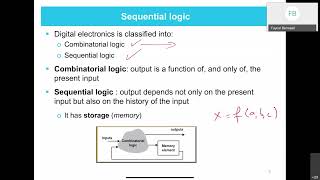
In this section, we explore the design of a Finite State Machine (FSM) for a traffic light controller using VHDL. An FSM is a model that can be in one of a finite number of states; in this case, the traffic light controller must cycle through three distinct states: RED, YELLOW, and GREEN.
Key Components of the FSM Design:
- Entity Declaration: The FSM starts with defining the entity,
traffic_light_fsm, which takes inputs forCLK(clock signal) andRESET(reset signal) and produces a 3-bit outputLIGHTthat indicates the current state of the traffic light.
-
Architecture Definition: The architecture is defined with a type
state_typeencompassing the statesRED,YELLOW, andGREENand two signals,stateandnext_state, to hold the current and next states. -
State Transitions: Logic for state transitions is captured within a process triggered by the clock and reset signals, resetting the machine to the
REDstate if RESET is active. Otherwise, on each clock edge, thenext_stateis assigned tostate. -
Next State Logic: Another process depends on the current
state, defining transitions: - From RED to GREEN,
- From GREEN to YELLOW,
- From YELLOW to RED.
-
Output Logic: Logic for the output
LIGHTcorresponding to each state ensures that the traffic lights are activated correctly: LIGHT=100(Red),LIGHT=010(Yellow),LIGHT=001(Green).
This design of an FSM for a traffic light controller effectively demonstrates how to implement state machines in VHDL, highlighting essential aspects such as state transitions and output mechanisms.
Youtube Videos


Audio Book
Dive deep into the subject with an immersive audiobook experience.
Entity Declaration for Traffic Light Controller
Chapter 1 of 5
🔒 Unlock Audio Chapter
Sign up and enroll to access the full audio experience
Chapter Content
-- Entity Declaration for Traffic Light Controller
type traffic_light_fsm is
port (
CLK : in std_logic;
RESET : in std_logic;
LIGHT : out std_logic_vector(2 downto 0) -- 3-bit output for traffic light (Red, Yellow,
Green)
);
end entity traffic_light_fsm;
Detailed Explanation
In this first chunk, we define the 'entity' for the traffic light controller using VHDL. An 'entity' represents the exterior of a digital module, specifying its inputs and outputs. Here, the traffic light FSM has three main ports: CLK (the clock input), RESET (to reset the traffic-light states), and LIGHT (a 3-bit output that will determine which light is on: Red, Yellow, or Green). The syntax here captures the essential characteristics of the traffic light system.
Examples & Analogies
Think of the entity declaration as the blueprint for a traffic light system. Just like an architect's blueprint shows the dimensions and components of a building (like doors and windows), this entity outlines the traffic light's main features (inputs and outputs) without delving into the mechanisms behind how it works.
Architecture Definition for Traffic Light FSM
Chapter 2 of 5
🔒 Unlock Audio Chapter
Sign up and enroll to access the full audio experience
Chapter Content
-- Architecture Definition for Traffic Light FSM
architecture fsm of traffic_light_fsm is
type state_type is (RED, YELLOW, GREEN);
signal state, next_state : state_type;
begin
... (remaining logic omitted for brevity)
end architecture fsm;
Detailed Explanation
In this chunk, we define the architecture of the traffic light FSM. We first create a custom data type named 'state_type' which includes three states: RED, YELLOW, and GREEN. We also declare two signals: 'state' (which holds the current state of the traffic light) and 'next_state' (which determines which state will come next). The architecture connects the entity to its internal logic, setting up the framework for how the traffic light will function during its operation.
Examples & Analogies
Imagine this architecture definition as the internal wiring of a traffic light. Just like how wires connect and direct power to different parts of the light, this definition sets the stage for how different states (the colors) are managed and transitioned. It ensures that when the light turns from RED to GREEN, there's a clear flow of 'electricity' (or logic) that dictates this change.
Process for State Transitions
Chapter 3 of 5
🔒 Unlock Audio Chapter
Sign up and enroll to access the full audio experience
Chapter Content
-- Process for state transitions
process (CLK, RESET)
begin
if RESET = '1' then
state <= RED; -- Reset to RED state
elsif rising_edge(CLK) then
state <= next_state;
end if;
end process;
Detailed Explanation
This chunk describes the process responsible for managing state transitions in the traffic light FSM. The process is triggered by changes in either the clock (CLK) or the reset signal (RESET). If RESET is activated (equal to '1'), the system resets to the RED state. If a clock pulse (rising edge) is detected, the FSM updates its current state to whatever the 'next_state' is determined to be. This process ensures that the traffic light only changes states based on defined triggers.
Examples & Analogies
Think of this logic as the control system in a traffic management center. When the reset button is pressed, the lights return to their initial state (RED), similar to how traffic controllers might restart signals after a malfunction. The clock pulse functions like a timer in this scenario, dictating when the lights should change based on a set schedule.
Next State Logic Based on the Current State
Chapter 4 of 5
🔒 Unlock Audio Chapter
Sign up and enroll to access the full audio experience
Chapter Content
-- Next state logic based on the current state
process (state)
begin
case state is
when RED => next_state <= GREEN;
when YELLOW => next_state <= RED;
when GREEN => next_state <= YELLOW;
end case;
end process;
Detailed Explanation
This chunk outlines how the next state of the traffic light is determined based on the current state. The 'process' examines the current state and, through a case structure, sets the next_state accordingly: if the current state is RED, the next state becomes GREEN; if YELLOW, the next state is RED; and if GREEN, it becomes YELLOW. This creates a continuous cycle of traffic light states.
Examples & Analogies
Imagine the logic of traffic lights as a well-coordinated dance. Each time a dancer reaches a certain position (the current state), they know their next move (next state). For instance, when the dancer (light) is in the RED position, they know to move to GREEN when it's time—continuously flowing through the choreography of traffic control.
Output Logic Based on the Current State
Chapter 5 of 5
🔒 Unlock Audio Chapter
Sign up and enroll to access the full audio experience
Chapter Content
-- Output logic based on the current state
process (state)
begin
case state is
when RED => LIGHT <= "100"; -- Red light
when YELLOW => LIGHT <= "010"; -- Yellow light
when GREEN => LIGHT <= "001"; -- Green light
end case;
end process;
Detailed Explanation
In this segment, we detail the output logic of the FSM, which defines what the actual outputs (traffic light signals) will be based on the current state. Each state corresponds to a specific binary output value: '100' for RED, '010' for YELLOW, and '001' for GREEN. This mapping efficiently translates the state of the FSM into visible light signals for drivers.
Examples & Analogies
Consider this output logic as the way a conductor instructs an orchestra to play. Each section has a specific role depending on the score (current state). Just like the conductor raises his baton to cue different sections at different times to create music, the traffic light controller lights up specific colors to guide drivers, ensuring safety and flow at intersections.
Key Concepts
-
FSM: A computational framework managing various states.
-
Entity Declaration: defines inputs and outputs for the FSM.
-
Architecture: specifies how the FSM functions.
-
State Transitions: logic defining movement between states.
-
Output Logic: mechanism determining output for each state.
Examples & Applications
Traffic light FSM cycling through Red, Yellow, Green states.
A pedestrian crossing controller using FSM principles to manage signals based on states.
Memory Aids
Interactive tools to help you remember key concepts
Rhymes
Red means stop, Green means go, Yellow's a warning, take it slow!
Stories
Imagine a traffic officer guiding the lights, changing from Red to Green as cars come forth while Yellow cautions to slow down.
Memory Tools
Think RYG for remembering the traffic light colors in order: Red, Yellow, Green.
Acronyms
RYG
Red
Yellow
Green is the cycle order in traffic lights.
Flash Cards
Glossary
- Finite State Machine (FSM)
A computational model consisting of a finite number of states, transitions, and outputs used to design sequential logic.
- VHDL
VHSIC Hardware Description Language, a language used for describing the structure and behavior of electronic systems.
- Clock Signal (CLK)
A signal used to synchronize operations of a circuit by providing regular timing pulses.
- Reset Signal
A control signal that initializes a system to a default state.
- State Transition
The movement from one state to another within a system based on inputs.
- Output Logic
The logic that determines what outputs correspond to each state in an FSM.
Reference links
Supplementary resources to enhance your learning experience.