
Energy Losses in Parallel Pipes
Enroll to start learning
You’ve not yet enrolled in this course. Please enroll for free to listen to audio lessons, classroom podcasts and take practice test.
Interactive Audio Lesson
Listen to a student-teacher conversation explaining the topic in a relatable way.
Velocity Defect and Energy Loss
🔒 Unlock Audio Lesson
Sign up and enroll to listen to this audio lesson

Today, we're going to dive into the concept of velocity defects in fluid flow. Can anyone tell me what a velocity defect is?

Isn't it the difference between the actual fluid velocity and the average velocity?
Exactly, great answer! This difference can lead to significant energy losses, especially in turbulent flows. When we measure these deviations, we often refer to them using an alpha value, which can be experimentally derived.

How does this alpha value affect our calculations?
Good question! The alpha value helps us quantify energy losses by adapting our head loss equations. For instance, if alpha equals 0.4, that indicates a significant level of turbulence affecting our calculations.

Can you give an example of how we would calculate this?
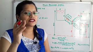
Sure! We can calculate head loss using the Darcy-Weisbach equation, which integrates velocity, pipe length, and friction factors. Remember this formula to guide you: H_f = f*(L/D)*(V^2/2g).
To summarize, understanding velocity defects is essential for calculating energy losses in pipes, especially under turbulent conditions.
Energy Loss Calculations in Series vs. Parallel Pipes
🔒 Unlock Audio Lesson
Sign up and enroll to listen to this audio lesson

Now, let’s compare energy losses in pipes arranged in series versus parallel. How does the energy loss change?
In series, we add up all the losses, right?
Correct! The total head loss is simply the sum of individual head losses from each pipe. And can someone tell me about the energy losses in parallel pipes?
All paths must have the same energy loss, right? Even if the flows are different.
Exactly! Because energy loss must be equal for all parallel paths, we can use flow rates to analyze how much fluid goes through each pipe.

What if we have minor losses due to fittings or diameter changes?
Minor losses should always be considered, both in series and parallel systems. They can significantly impact our total head loss calculations. Remember, the total loss in a parallel setup includes both major and minor losses.
In summary, energy loss calculation varies significantly between series and parallel pipe systems. Always remember to account for all minor and major losses!
Three Reservoir Junction Problems
🔒 Unlock Audio Lesson
Sign up and enroll to listen to this audio lesson
Let's apply what we've discussed to a practical scenario: the three reservoir junction problem. Who can explain what we're looking at here?
We have multiple water reservoirs connected by pipes, right? And the total flow into the junction must equal the outflow?
That's correct! The principle of mass conservation plays a key role. The discharge at this junction needs to equal zero when considering all flow directions.
What about the energy levels at the junctions?
Good point! The hydraulic gradient needs to be consistent across the junction to maintain balance. We can calculate head losses and ensure that the hydraulic gradient remains level.
How does this apply to real-world systems?
In real-life engineering, these problems help design effective pipeline systems. By understanding how energy is conserved and lost, we can better manage water supplies in urban settings.
To wrap up, mastering the dynamics at junctions is crucial for effective fluid management in engineering.
Applying Energy Loss Principles
🔒 Unlock Audio Lesson
Sign up and enroll to listen to this audio lesson
Now let’s work through some example problems to solidify our understanding. Can anyone set up the first example involving parallel pipes?
We have two parallel pipes of differing diameters, and we want to find the flow distribution!
That's a great start! What equations will we use?
We’ll use the continuity equation and the head loss equations!
Exactly! By applying both principles, we can find the distribution of flow in each pipe based on their respective diameters. Let's write out our main equations.
Should we also consider minor losses while calculating total head loss?
Certainly! Always remember to include minor losses, such as entry and exit losses, in your total calculations.
In conclusion, applying our knowledge of energy losses through practical problems helps us better understand fluid dynamics in real-world scenarios.
Introduction & Overview
Read summaries of the section's main ideas at different levels of detail.
Quick Overview
Standard
The section details the principles of energy losses in parallel pipes, emphasizing critical concepts such as velocity distribution, energy head losses, and the implications of pipe configurations on fluid flow. It includes discussions on steady-state conditions, minor and major losses, and provides practical examples and problems to illustrate these concepts.
Detailed
Energy Losses in Parallel Pipes
This section delves into the complexities of energy losses in parallel piping systems, which is crucial for understanding fluid dynamics in engineering applications. We begin with foundational concepts such as velocity defects, where we observe deviations from average velocities, and how they relate to turbulent flows. Utilizing dimensional analysis and experimental data, such as those from Nikuradse’s experiments, we derive formulae to quantify these velocity distributions and their impact on shear and average velocities.
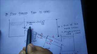
In the context of pipe configurations, we differentiate between pipes arranged in series versus those in parallel. For pipes in series, total head loss is the summation of individual losses, taking into account both major (frictional) and minor losses due to fittings and changes in diameter. On the other hand, when analyzing parallel pipes, it is crucial to recognize that energy losses through each pipe must be equal, despite variations in flow rates and velocities. This leads us to concepts such as the continuity equation, which dictates that the sum of flow rates entering a junction must equal zero in a three-reservoir problem scenario.
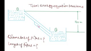
Practical examples, including problems from GATE exams, illustrate the application of these principles in real-world settings. By calculating head losses and applying continuity equations, we can efficiently model and predict fluid behavior in complex piping systems.
Youtube Videos


Audio Book
Dive deep into the subject with an immersive audiobook experience.
Understanding Energy Losses
Chapter 1 of 4
🔒 Unlock Audio Chapter
Sign up and enroll to access the full audio experience
Chapter Content
When you have a pipe in parallel, you can understand it as there are three pipes connected here. This is the A is the entry point, B is the exit point. From this point to this point, the total energy losses passing through this path A or path B or path C should be equal. So energy losses should be equal, whether following a path A, path B, or path C, all the energy losses should be equal.
Detailed Explanation
In a parallel pipe configuration, multiple pathways allow fluid to flow from one point to another. It is essential that the energy losses encountered in each pathway (A, B, or C) are equal. This is because, for steady flow conditions, energy conservation dictates that the total energy head loss must be conserved across different routes. What this means is that regardless of which path the fluid takes, the relationship between flow rates and energy losses remains consistent.
Examples & Analogies
Think of it like a network of roads where multiple routes lead to the same destination. Regardless of which road you take, the total time taken due to traffic, road conditions, and speed limits (akin to energy losses) will be similar when averaged out. If one road has a lot of stops, another has smooth driving, but, overall, the experience would be comparable in terms of time taken to reach the destination.
Flow Distribution in Parallel Pipes
Chapter 2 of 4
🔒 Unlock Audio Chapter
Sign up and enroll to access the full audio experience
Chapter Content
As the flow is coming and divide into three parts, we can always write the Q what is coming it will be distributed into the three parts in this figure. So, as you have a branching out, you can converge the flow. The sum of the discharges will give us the discharge passing through the A or B, and the energy losses whether following path 1, 2, or 3 should be equal.
Detailed Explanation
In a parallel pipe system, the total discharge (or flow rate) splits among various paths, such as the pipes A, B, and C. The total inflow to these pipes must equal the outflow at the exit (or junction). Therefore, it can be stated mathematically that the sum of flow rates through all paths equals the total incoming flow. The essential equality of energy losses across these paths reinforces this flow distribution, emphasizing that the pipes must function under comparable energy losses for the flow to maintain continuity.
Examples & Analogies
Imagine a garden hose dividing water flow into several smaller hoses, each leading to different plants. The total water coming from the main source must equal the sum of water flows from each hose. If each hose has obstacles that slow down the water (similar to energy losses), then the system's efficiency determines how well each plant gets water, similar to ensuring the energy loss remains balanced.
Hydraulic Gradient and Flow Contribution
Chapter 3 of 4
🔒 Unlock Audio Chapter
Sign up and enroll to access the full audio experience
Chapter Content
At the junction point, the continuity equations for mass conservation should equal zero. The hydraulic gradient, which represents the energy level available due to elevation, is important to estimate the head losses happening. If you compute the hydraulic gradients, you can find out the flow contributions through various branches or pipes.
Detailed Explanation
In fluid dynamics, the hydraulic gradient represents the change in the hydraulic head (energy per unit weight) along the flow. When fluid flows through junctions in parallel systems, it is essential to analyze the energy levels to determine how much energy is lost due to friction and other factors. By understanding the hydraulic gradient at various points, engineers can calculate the expected flow contributions through different pipes and ensure that they function within the desired parameters.
Examples & Analogies
Think of it like water flowing downhill. If you picture various streams coming together at a fork, understanding the elevation (hydraulic gradient) helps predict which stream will have more flow. If one has a steeper slope, more water will flow through it, while others may stagnate, similar to ensuring that your energy losses across various paths maintain a balance.
Three Reservoir Junction Problems
Chapter 4 of 4
🔒 Unlock Audio Chapter
Sign up and enroll to access the full audio experience
Chapter Content
Now, if you look at the three-reservoir junction problems, you may have multiple tanks connected to the pipe flow systems. The continuity equations at these junctions should equal zero. This means, at the junction point, the sum of the discharge through each reservoir must equal outflow, factoring in any possible head losses.
Detailed Explanation
In scenarios involving multiple reservoirs connected through pipes, it is critical to apply the principle of mass conservation. At the junction where waters from various tanks converge, the total inflow must equal the outflow. By analyzing the relationships between the hydraulic gradients and energy losses at the junction, one can derive the necessary equations to ascertain the flow contributions and quantify head losses due to friction or other factors.
Examples & Analogies
Consider a city with multiple water storage tanks feeding into a main distribution pipe. All tanks need to provide a balanced outflow into the main distribution line, analogous to ensuring that all reservoirs contribute equally to maintain a steady water level in the system. If one tank has a restriction due to debris, it would affect the water availability downstream, similar to head losses that must be accounted for in the junction analysis.
Key Concepts
-
Velocity Defect: The concept of the difference between actual and average flow velocity, important in analyzing turbulent flows.
-
Head Loss: A critical metric in fluid dynamics, representing energy loss due to friction and other factors in pipes.
-
Series vs. Parallel Flow: Understanding the difference in energy loss calculations between series and parallel pipe arrangements.
Examples & Applications
Example of calculating head loss in a straight pipe due to friction.
Example problem involving flow distribution in two parallel pipes of different diameters.
Memory Aids
Interactive tools to help you remember key concepts
Rhymes
In a pipe where fluids flow, head loss rises high, just so.
Stories
Imagine a river flowing over rocks. Each rock causes a splash, which represents head loss—a reminder that every obstacle will slow our flow.
Memory Tools
Think of 'M.' for Major losses, 'm.' for minor losses. Major means friction, minor means changes in flow direction.
Acronyms
V.H.E. - Velocity defect, Head loss, Energy loss.
Flash Cards
Glossary
- Velocity Defect
The difference between the average velocity of a fluid and the actual velocity, particularly in turbulent flow.
- Head Loss
The energy loss due to friction and other factors in a fluid flowing through a pipe.
- Minor Losses
Energy losses due to fittings, bends, valves, and changes in diameter in a piping system.
- Major Losses
Energy losses primarily due to friction as fluid flows through a pipe.
Reference links
Supplementary resources to enhance your learning experience.