
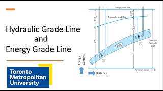
Hydraulic Gradient Line
Enroll to start learning
You’ve not yet enrolled in this course. Please enroll for free to listen to audio lessons, classroom podcasts and take practice test.
Interactive Audio Lesson
Listen to a student-teacher conversation explaining the topic in a relatable way.
Introduction to Hydraulic Gradient Line
🔒 Unlock Audio Lesson
Sign up and enroll to listen to this audio lesson

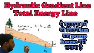
Today, we will explore the hydraulic gradient line, which is essential for understanding how pressure changes within a fluid system.

What exactly does the hydraulic gradient line tell us?
Great question! The hydraulic gradient line indicates the pressure head at various points along a flow system. It’s crucial for identifying energy losses.

How do those pressure changes affect flow?
The changes directly impact flow rates and velocity, which must be calculated to ensure efficient flow.

Can you elaborate on how we calculate those pressures?
We use formulas derived from dimensional analysis and experiments, like the Nikuradse experiment, to derive head losses due to friction.
So remember this: the acronym 'HEAD' can help you remember: Hydraulic Gradient, Energy Analysis, And Dynamics.

Got it! That makes it easier to recall!
Excellent! In summary, the hydraulic gradient line is critical for visualizing and calculating fluid pressure in systems.
Flow in Pipelines: Series and Parallel
🔒 Unlock Audio Lesson
Sign up and enroll to listen to this audio lesson

Moving on, let’s discuss pipes in series versus pipes in parallel. Who can tell me how they differ?
In series, water goes from one pipe to another, right?
Exactly! And in this configuration, the total head loss is the sum of individual losses. How do we express that?
By adding them up! Like delta h 1 plus delta h 2, etc.
Correct! Now let's switch gears—what about pipes in parallel?
In parallel, flow splits into multiple paths, right?
Exactly. And here, total energy losses along each path should be equal. Can someone tell me why?
Because the flow is split, but the energy must be conserved across all paths!
Fantastic response! In short, knowing the differences in pipe configurations helps us calculate flow and losses accurately.
Energy Losses in Flow Systems
🔒 Unlock Audio Lesson
Sign up and enroll to listen to this audio lesson
Now, let's explore energy losses in our systems. Can anyone tell me what major losses are?
Those are the friction losses in the pipe.
Correct! And minor losses? What might those include?
They include losses from fittings, bends, or diameter changes.
Exactly! When calculating total head loss, we combine both major and minor losses. How would we express that mathematically?
By using total head loss equals major losses plus minor losses!
Yes! Remember, always acknowledge minor losses when calculating to get a real-world picture. Use the acronym 'MILE' for Minor and Major In Loss Evaluations!
That’s a handy mnemonic!
Fantastic work today! So remember: both major and minor losses dramatically impact our hydraulic gradient calculations.
Three Reservoir Junction Problems
🔒 Unlock Audio Lesson
Sign up and enroll to listen to this audio lesson
Let’s apply what we've covered to a more complex system: the three reservoir junction problem. What is key in solving these?
Understanding the flow directions and their corresponding energy levels?
Exactly! Each junction must maintain mass conservation. If one flow is an outflow, what equation explains that?
The sum must equal zero!
Spot on! Also, we must equate energy losses properly. Can someone illustrate what that might look like?
We could use the hydraulic gradient lines to measure head losses at each junction!
Perfect example! The hydraulic gradient and energy lines must align for balanced flow. Let’s remember the phrase: 'Flow Follows the Line' -- for understanding hydraulic gradient lines in practice.
That helps visualize it!
Excellent engagement! In summarizing, ensure you account for hydraulic gradients when approaching junctions as they dictate flow behavior.
Introduction & Overview
Read summaries of the section's main ideas at different levels of detail.
Quick Overview
Standard
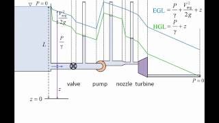
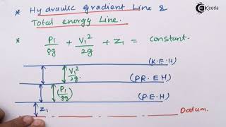
The hydraulic gradient line represents pressure changes across a flow system, showcasing how energy losses due to friction and fittings affect overall flow. In this section, concepts like flow in series and parallel pipes, minor and major losses, and the use of dimensional analysis in hydraulic calculations are explored.
Detailed
In fluid dynamics, the hydraulic gradient line is critical for analyzing how pressure changes along a flow path. This section presents various concepts including the velocity defect, energy losses due to friction in both major and minor forms, and the application of dimensional analysis. By using equations derived from experiments (such as Nikuradse's), we can determine parameters like average and shear velocities in turbulent flows. The section goes on to describe scenarios involving pipes in series and parallel, illustrating how to calculate head losses while maintaining mass continuity. Furthermore, the practical implications of the hydraulic gradient line in real-world applications, like three reservoir junction problems, are discussed, emphasizing the importance of accurate energy gradient calculations.
Youtube Videos
![Hydraulic and Energy Grade Line ? with animation [ HGL and EGL ]](https://img.youtube.com/vi/moI4DQNirAw/mqdefault.jpg)
Audio Book
Dive deep into the subject with an immersive audiobook experience.
Velocity Defect Concept
Chapter 1 of 8
🔒 Unlock Audio Chapter
Sign up and enroll to access the full audio experience
Chapter Content
But if you go to the outer layers where we look it that a velocity defect concept, how far the velocity from average velocity, that the defect means how much deviations how much difference between that; if you look it that and looking.
Detailed Explanation
The velocity defect concept examines how the actual flow velocity in a fluid differs from the average velocity. This difference, or 'defect', represents deviations in flow characteristics, particularly in turbulent flows. It's significant in understanding how velocity varies with distance from a boundary, like a pipe wall.
Examples & Analogies
Imagine a group of runners on a track. While some runners may maintain a steady pace (average velocity), others may speed up or slow down due to various factors like fatigue or an inclination. The differences in their speeds compared to the average can be thought of as their velocity defects.
Dimensional Analysis and Experimental Findings
Chapter 2 of 8
🔒 Unlock Audio Chapter
Sign up and enroll to access the full audio experience
Chapter Content
We again we get the similar functions from the dimensional analysis between V and y and h. Now if you look it that, if you put it high turbulence flow and the velocity the reasons is very this is called velocity deflect law and h is replaced by the R the pipe radius...
Detailed Explanation
Through dimensional analysis, relationships between variables like flow velocity (V), distance from a surface (y), and pipe radius (h/R) can be derived. In high turbulence flows, these variables interact in specific ways, leading to empirical formulas that help engineers predict behavior in flowing systems.
Examples & Analogies
Think about how water behaves in a fast-moving river. Near the banks (surface), the flow may be slower compared to the middle of the river where the flow is swift. Dimensional analysis helps engineers understand these variations and predict how changes in the river's conditions, such as width or depth, might affect flow.
Logarithmic Overlap Layers
Chapter 3 of 8
🔒 Unlock Audio Chapter
Sign up and enroll to access the full audio experience
Chapter Content
And more details if in a overlap zones you will have a this equation. So now if you look it from the experiment and the dimensional analysis using this Nikuradse experiment data set it was found what could be the alpha value...
Detailed Explanation
In flow systems, layers can experience overlapping behaviors, often called overlap zones. Experimental studies like Nikuradse's provide insights into how velocity and shear stress relate within these zones. The parameter 'alpha', typically found to be 0.4, captures the characteristics of how flow behaves in these scenarios.
Examples & Analogies
Consider a busy highway merging into a single lane. Initially, lanes are moving smoothly, but as they converge, some cars slow down (the overlap effect). Understanding how velocity changes in such zones helps traffic engineers improve flow through design.
Pipes in Series
Chapter 4 of 8
🔒 Unlock Audio Chapter
Sign up and enroll to access the full audio experience
Chapter Content
Now we coming back to the very simple examples okay. And that is what is in your text book is necessary to for. If you look it that, many of the times you have the pipes in series...
Detailed Explanation
In fluid mechanics, when pipes are connected end to end (in series), the total discharge or flow rate remains constant. The energy loss across the entire system is the sum of individual head losses due to friction in each pipe. Calculating these losses helps determine the overall performance of a series piping system.
Examples & Analogies
Imagine a water hose leading into multiple buckets. As water flows through each bucket, the total amount of water exiting the last bucket will be the same as the water entering the first, but some will be 'lost' due to the bucket's resistance (frictional loss).
Pipe Energy Losses
Chapter 5 of 8
🔒 Unlock Audio Chapter
Sign up and enroll to access the full audio experience
Chapter Content
But when you have a pipe in a series please remember it that you always should consider whether there is a minor losses...
Detailed Explanation
When assessing energy losses in pipes, it’s crucial to not only account for major losses due to friction but also minor losses due to fittings, bends, and changes in diameter. Accurately quantifying these losses ensures more precise predictions of flow rates and energy requirements.
Examples & Analogies
Think of a rollercoaster: smooth tracks represent major losses (friction), while steep turns and loops act like minor losses that affect the overall energy needed to complete the ride. Just like rollercoaster designers must factor in every curve, engineers must account for each minor loss in a piping system.
Pipes in Parallel
Chapter 6 of 8
🔒 Unlock Audio Chapter
Sign up and enroll to access the full audio experience
Chapter Content
Now if you look it another very simple problems that pipes in parallel...
Detailed Explanation
When pipes are arranged in parallel, the total flow divides among the pipes. The energy losses must be equal across all pathways due to conservation of energy principles. Understanding this balance is vital for ensuring that flow is appropriately shared among branches without causing backups.
Examples & Analogies
Imagine branching river tributaries that flow into a larger river. If one tributary has a dam (representing friction), all tributaries must adjust their flows so that the water level remains constant downstream. This is similar to how parallel pipes must adjust their flow rates based on the energy losses.
Three Reservoir Junction Problems
Chapter 7 of 8
🔒 Unlock Audio Chapter
Sign up and enroll to access the full audio experience
Chapter Content
Now if you look it the three reservoir junction problems which many of the time it is given that you have a multiple reservoirs...
Detailed Explanation
In situations with multiple reservoirs, continuity equations help ensure that the total flow is conserved at junctions. At these points, flows may divide or converge, and understanding the hydraulic gradient allows engineers to compute potential head losses and flow directions.
Examples & Analogies
Visualize a park with several ponds (reservoirs) connected by streams (pipes). If one pond overflows, the additional water will flow into the lower ponds, but how much goes where depends on the connections and current water levels. Similarly, engineers must calculate flow paths between reservoirs to maintain balance.
Calculating Minimum Gradient
Chapter 8 of 8
🔒 Unlock Audio Chapter
Sign up and enroll to access the full audio experience
Chapter Content
Let us start this third examples which is gives that 2 kilometer long pipe with a diameter of 0.2 meter diameter connects two reservoirs...
Detailed Explanation
To ensure adequate flow through a pipe system between two reservoirs, accounting for frictional losses and providing a sufficient gradient is essential. The minimum gradient required can be derived by balancing chemical energy losses in the system, ensuring effective flow from one reservoir to the other.
Examples & Analogies
Think about water flowing downhill in a garden. If the slope is too shallow, the water may not reach its destination efficiently. Similarly, if engineers don’t provide enough gradient to counteract friction, water in pipes may 'get stuck' and fail to flow.
Key Concepts
-
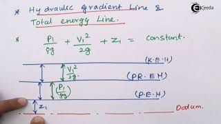
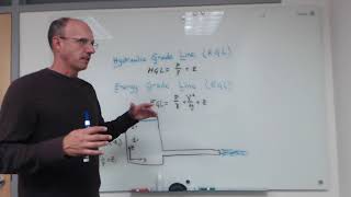
Hydraulic Gradient Line: Reflects pressure changes in flow systems.
-
Head Loss: A decrease in energy due to friction and turbulence.
-
Major Losses vs. Minor Losses: Major losses are due to friction, while minor losses arise from fittings and transitions.
Examples & Applications
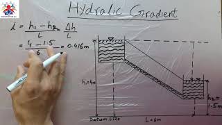
Example 1: Calculating hydraulic gradient line for a flowing pipe with known pressure and elevation data.
Example 2: Solving for the total head loss in a parallel pipe arrangement with varying diameters.
Memory Aids
Interactive tools to help you remember key concepts
Rhymes
In pipes where the flow isn’t slow, friction causes energy to go, keep it in mind, so flow doesn’t slow!
Stories
Imagine a water park where rivers flow through tubes. Each tube (pipe) has some resistance, but some also have twists and turns (fittings). The water levels (energy) drop as it flows, losing some power to each twist and turn!
Memory Tools
Remember 'HEAD' for Hydraulic Gradient, Energy Analysis, And Dynamics.
Acronyms
MILE = Major and Minor In Loss Evaluations.
Flash Cards
Glossary
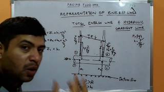
- Hydraulic Gradient Line
A graphical representation of changes in pressure head across points in a flow system.
- Head Loss
The reduction in total energy along a flow path due to friction and turbulence.
- Major Losses
Energy losses primarily due to friction in pipes.
- Minor Losses
Energy losses related to fittings, bends, and entrances/exits in flow.
Reference links
Supplementary resources to enhance your learning experience.