
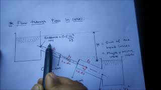
Pipes in Series
Enroll to start learning
You’ve not yet enrolled in this course. Please enroll for free to listen to audio lessons, classroom podcasts and take practice test.
Interactive Audio Lesson
Listen to a student-teacher conversation explaining the topic in a relatable way.
Introduction to Pipes in Series
🔒 Unlock Audio Lesson
Sign up and enroll to listen to this audio lesson

Today, we will explore how fluid flows through pipes connected in series. Why do you think it is important to understand this concept?

I think it helps in designing plumbing systems.
Exactly! In a series setup, the flow rate remains constant, so the discharge is equal across all pipes. Let's remember this with the acronym 'Q = Constant'.

What happens if we have different diameters of pipes?
Good question! That leads us to discuss head loss and energy computations. Head losses due to friction will vary with diameter. Can anyone tell me what major losses are?

Those are the losses due to friction in the pipe, right?
Exactly! Major losses are primarily due to friction. Remember, for pipes in series, the total energy loss is the sum of losses in each pipe.
Calculating Head Loss
🔒 Unlock Audio Lesson
Sign up and enroll to listen to this audio lesson

Let's proceed to calculate head loss. Can anyone recall the formulae for major losses?

It's the Darcy-Weisbach equation, right?
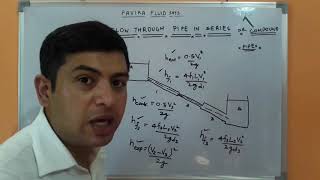
Correct! For a single pipe, the head loss can be calculated using the formula: h_f = f * (L/D) * (V^2/2g). What do we need to account for if we have multiple pipes?
We need to add up the head losses from each pipe together.
Exactly! So if we have n pipes, the total head loss can be expressed as: H_total = h_f1 + h_f2 + ... + h_fn, where each h_f is calculated for each individual pipe.
What about minor losses?
Great observation! Minor losses should also be included, especially at junctions or when the pipe diameter changes. So, remember: Total Head Loss = Major Losses + Minor Losses.
Practical Examples
🔒 Unlock Audio Lesson
Sign up and enroll to listen to this audio lesson
Let’s apply our knowledge to some examples. If we have three pipes with given lengths and diameters, how do we approach calculating the total head loss?
We first find the head loss for each pipe individually using the Darcy-Weisbach equation, and then sum them up!
And don’t forget to calculate the minor losses if there are any diameter changes or bends!
Exactly! Always remember to include both major and minor losses for accurate calculations. Let’s summarize: Q remains constant in series, calculate head losses for each pipe, and sum them up along with minor losses. Can anyone give an example of when you might encounter this in daily life?
In household plumbing, pipes are often connected in series!
Absolutely! Applying these concepts can help us design more efficient plumbing systems.
Introduction & Overview
Read summaries of the section's main ideas at different levels of detail.
Quick Overview
Standard
In this section, we explore the behavior of fluid flow through pipes in series, highlighting how steady flow conditions maintain a constant discharge across all connected pipes. It also covers the significance of calculating total head loss, incorporating both major and minor losses during fluid transport in pipe systems.
Detailed
In this section, we examine the flow behavior of incompressible fluids through pipes connected in series. The discharge remains constant across all pipes, indicative of steady-state conditions. The total head loss is calculated as the sum of individual head losses from each pipe, accounting for both major losses due to friction and minor losses from diameter changes, exit, and entry losses. Understanding the principles of energy losses allows for better design and analysis of complex pipe networks.
Youtube Videos


Audio Book
Dive deep into the subject with an immersive audiobook experience.
Introduction to Pipes in Series
Chapter 1 of 5
🔒 Unlock Audio Chapter
Sign up and enroll to access the full audio experience
Chapter Content
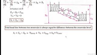
If you look at many of the times you have the pipes in series, pipes in parallel or three reservoir junction problems. Pipe in series is a very simple problem like electric circuits. If you have a series of wires from point A to B, the discharge will be for a steady state conditions.
Detailed Explanation
This chunk introduces the concept of pipes in series, likening them to electric circuits where multiple wires are connected end-to-end. In a pipe system, if these pipes are arranged in series, it means they are connected one after another. When fluid flows through these pipes in a steady state, the discharge (amount of fluid passing through) remains constant across each pipe, which is a key characteristic of series systems.
Examples & Analogies
Think of a line of cars driving through a tunnel. Each car represents a unit of fluid flowing through the pipe. As one car exits the tunnel, another enters at the same rate, similar to how fluid flows through a series of connected pipes without any changes in flow rate.
Discharge Consistency
Chapter 2 of 5
🔒 Unlock Audio Chapter
Sign up and enroll to access the full audio experience
Chapter Content
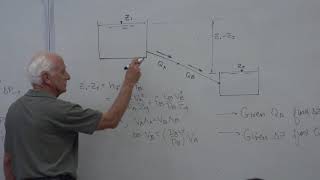
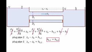
For steady flow conditions, discharge Q1, Q2, Q3 should equal because this is a steady state.
Detailed Explanation
In a steady flow situation, the amount of fluid entering each section of the series of pipes must be equal to the amount exiting. This means that the discharge, represented by Q (flow rate), must be constant regardless of the specific details of each pipe. So if we have Q1, Q2, and Q3 representing the discharges through three pipes in series, they must all be equal: Q1 = Q2 = Q3.
Examples & Analogies
Imagine a chain of people passing buckets of water along a line. Each person passes the same amount of water they received to the next person, ensuring that no one runs out of water. This reflects how discharge is maintained constant in pipes in series.
Energy Losses in Pipes
Chapter 3 of 5
🔒 Unlock Audio Chapter
Sign up and enroll to access the full audio experience
Chapter Content
But if you are having energy losses between pipes, the total head loss is the sum of the head losses of individual pipes connected in series.
Detailed Explanation
While fluid flow is steady, energy losses can occur due to friction and other factors as the fluid moves through each pipe. These losses result in a decrease in the energy or 'head' of the fluid. The total head loss in a series of pipes is equal to the sum of the losses in each pipe, meaning if Pipe 1 has a head loss of Δh1 and Pipe 2 has Δh2, then the total head loss, Δh_total, would be Δh1 + Δh2.
Examples & Analogies
Think of water flowing down a slide that has several bumps. Each bump causes the water to lose some speed and energy. The total energy lost while going down the slide is the same as the sum of energy lost at each bump along the way. Similarly, in pipes, every section can cause energy loss.
Major and Minor Losses
Chapter 4 of 5
🔒 Unlock Audio Chapter
Sign up and enroll to access the full audio experience
Chapter Content
Please remember that you always should consider minor losses along with major losses, which include frictional losses. There may be contraction, expansion, exit losses and entry losses.
Detailed Explanation
When calculating total energy losses in pipes, one must consider both major losses (primarily due to friction along the pipe) and minor losses caused by changes in flow conditions, such as when the pipe diameter changes or when the fluid enters or exits the pipe. This holistic approach ensures a more accurate estimation of total energy loss and thus better management of the fluid system.
Examples & Analogies
Imagine driving a car on a road with various conditions. The friction of the asphalt (major loss) slows you down, but construction barriers and merging lanes (minor losses) may slow you down even more. Both types of conditions need to be considered to know when you'll reach your destination.
Summation of Head Losses
Chapter 5 of 5
🔒 Unlock Audio Chapter
Sign up and enroll to access the full audio experience
Chapter Content
The head energy losses along the pipe from Pipe 1, Pipe 2, and Pipe 3 can be represented as a summation of head losses: h_total = Δh1 + Δh2 + Δh3.
Detailed Explanation
To compute the total head loss in a series of pipes, one would take the head loss from each pipe and add them together. This provides a clear picture of how much energy the fluid has lost as it moves through the entire system of connected pipes.
Examples & Analogies
Consider a marathon runner who stops to drink water at several stations. Each drink stops slows them down, and at the end of the race, the time added from all stops accumulates. Just like the runner's total time taken equals the sum of each stop's delay, the total head loss equals the sum of losses from each section of the pipe.
Key Concepts
-
Flow in Series: Understanding that the flow rate remains constant through pipes connected in series.
-
Head Loss: Recognizing the significance of calculating head loss due to both major and minor losses.
-
Energy Loss Computation: Learning to compute total energy loss by adding head losses from individual pipes.
Examples & Applications
When designing a plumbing system for multiple floors in a building, ensuring even water pressure by calculating pipe lengths and diameters in series.
In irrigation systems, flow rates in a series of pipes must be calculated to ensure sufficient water delivery across all areas.
Memory Aids
Interactive tools to help you remember key concepts
Rhymes
Pipes in series flow with glee, losses add up one, two, three.
Stories
Imagine a train with multiple cars, each representing a pipe. If one car feels heavier due to friction, the whole train slows down—just like head loss in pipes affects the whole flow.
Memory Tools
To remember head losses, think 'H = M + m' where H is total head loss, M is major, and m is minor losses.
Acronyms
For 'Pipes in Series,' think of 'P.I.S.'
Pressure In Series—pressure remains consistent.
Flash Cards
Glossary
- Head Loss
The reduction in total mechanical energy due to friction or other resistive forces in a fluid as it flows through a pipe.
- Major Losses
The losses in head due mainly to friction along the length of the pipe.
- Minor Losses
The losses that occur at fittings, bends, transitions, or changes in diameter of a pipe, which can affect the flow.
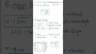
- DarcyWeisbach Equation
An equation used to calculate the head loss due to friction in a fluid flowing through a pipe.
- Steady Flow
A condition where the fluid's velocity and other properties at any point in the system remain constant over time.
Reference links
Supplementary resources to enhance your learning experience.