
Pipes in Parallel
Enroll to start learning
You’ve not yet enrolled in this course. Please enroll for free to listen to audio lessons, classroom podcasts and take practice test.
Interactive Audio Lesson
Listen to a student-teacher conversation explaining the topic in a relatable way.
Introduction to Parallel Pipe Flow
🔒 Unlock Audio Lesson
Sign up and enroll to listen to this audio lesson

Today, we're going to discuss how fluid flows through pipes arranged in parallel. Can anyone tell me what happens to energy losses in this scenario?

Doesn't the energy loss have to be the same for each pipe since they connect the same two points?
Exactly! The energy losses must equalize across each parallel path connecting points A and B. We can simplify this concept by remembering 'Parallel Paths = Equal Energy Losses' or PEEL.

What kind of energy losses are we looking at?
Great question! We consider both major losses due to friction in the pipes and minor losses from changes in diameter or direction. Together, they help us find the total head loss.

So, all paths have to share the same head loss?
That’s right! Since all paths must have equivalent energy losses, it leads us to specific calculations to manage flow optimally.
Understanding Discharge in Parallel Pipe Systems
🔒 Unlock Audio Lesson
Sign up and enroll to listen to this audio lesson

As fluids flow through parallel pipes, what happens to the discharge being distributed among them?
I think the total discharge remains constant, right?
Correct! We denote total discharge by the formula Q_total = Q1 + Q2 + Q3... If we change the path, the flow divides among the branches while maintaining the same total.

How does that relate to head losses?
Since the head loss is equally distributed, we can analyze each path's flow rate based on its diameter or friction factor to maintain the flow.
And if one pipe is wider than the others?
Good observation! Wider pipes typically allow for higher discharge rates, leading to a more complex relationship between diameter and flow. Never forget: 'Larger Pipe = Larger Q!'
Applying the Junction Condition in Parallel Pipe Systems
🔒 Unlock Audio Lesson
Sign up and enroll to listen to this audio lesson
Now let's look at junction problems with multiple reservoirs connected to pipe systems. What do we need to consider here?
Is it about ensuring the mass conservation at the junctions?
Exactly! We apply the continuity equation where the sum of all discharges at the junction should be zero, reflecting mass balance.
What about energy loss at these junctions?
Good point! The energy gradient must equalize at the junctions, so we often need to calculate the energy loss and hydraulic gradient at those critical points. Remember, 'Energy at Junction = Hydraulic Balance'!
So, if I understand correctly, we evaluate how much energy is used in losses to compute the needed headfall?
That's correct! Managing head loss effectively allows us to plan how to design our pipelines for optimal function.
Example Problem: Finding Discharge across Parallel Pipes
🔒 Unlock Audio Lesson
Sign up and enroll to listen to this audio lesson
Let's solve an example problem together regarding water flowing through two parallel pipes. How do we start?
We should sketch the setup first to visualize it properly.
Great strategy! After sketching, we need to identify the known values: diameter, length, and head difference.
Then we can set up our equations based on head losses between both pipes?
Exactly! By equating head losses and knowing our diameters, we can solve for the velocity ratios.
This seems like a practical way to apply what we've learned about energy losses!
Yes, it clearly illustrates how theoretical knowledge translates into practical problem-solving. Remember, always check unit consistency!
Calculating Energy Losses in Parallel Pipe Systems
🔒 Unlock Audio Lesson
Sign up and enroll to listen to this audio lesson
To calculate energy losses in a parallel pipe system, what steps do we follow?
We start by determining major losses from friction, right?
Correct! After calculating the friction loss, we also need to account for minor losses that result from pipe fittings and connections.
If pipe sizes change, how do they affect our calculations?
Changes in pipe diameter can greatly change the flow behavior and thus the dissipation of energy. It’s vital to apply proper calculations for accurate predictions.
And adjusting for all these variables can help ensure proper flow management in our systems?
Exactly! Effective management of energy losses is key in designing efficient and functional piping systems.
Introduction & Overview
Read summaries of the section's main ideas at different levels of detail.
Quick Overview
Standard
In this section, we examine how fluids travel through parallel pipes, noting that the total energy losses in each path must be equal. Additionally, we discuss the principles governing the discharge across parallel pipe systems and analyze junction scenarios involving multiple reservoirs.
Detailed
Pipes in Parallel
In this section, we delve into the mechanics of fluid flow through parallel pipes and the associated energy dynamics. The fundamental idea is that in a parallel configuration, energy losses must equalize across each pathway connecting two points (A to B). Here are the main points discussed:
- Energy Losses: The head losses experienced must be equivalent across all paths a fluid can take (A, B, or C), which is crucial for the system's balance.
- Discharge Distribution: As fluids branch out into multiple paths, the flow rate (discharge, Q) divides among the pipes while maintaining a constant total flow into the system.
- Head Loss Computation: An understanding of both major (friction losses) and minor losses (changes in pipe diameter) is essential to calculate the overall energy losses accurately.
- Junction Problems: We also detail situations involving three reservoir junctions where continuity equations govern the flow, emphasizing that their sum should equal zero in outflow scenarios. Interpreting the hydraulic gradients at these junctions is necessary for effective management of energy losses.
The reasoning behind these principles lays the groundwork for solving practical problems in engineering fluid mechanics, particularly in systems using multiple pipes in parallel configuration.
Youtube Videos


Audio Book
Dive deep into the subject with an immersive audiobook experience.
Introduction to Pipes in Parallel
Chapter 1 of 4
🔒 Unlock Audio Chapter
Sign up and enroll to access the full audio experience
Chapter Content
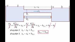
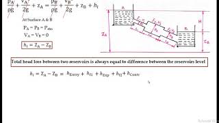
When you have a pipe in parallels, you can understand it see if I have the pipe in the parallels, there are three pipes are connected here. This is the A is entry point, B is exit point. From the this point to this point the total energy losses passing through this path A or path B or path C that should be equal. So energy losses should be equal, whether it follows a path A, path B, or path C, all the energy losses should be equal.
Detailed Explanation
In a system where multiple pipes run parallel to each other, the flow entering at a point (A) is divided among the pipes and exits at another point (B). The principle behind this setup is that regardless of which path the flow takes—through pipe A, B, or C—the total energy losses encountered along each path will be equal. This is crucial for ensuring that the flow splits correctly and that the system operates efficiently.
Examples & Analogies
Imagine a highway with multiple lanes. If all cars (the flow) enter the highway at a single point but can choose any lane (pipe A, B, or C) to reach the exit, each lane must have similar traffic conditions for the overall system to function smoothly. This ensures that no lane is overly congested while others are relatively empty, similar to how energy losses should be equal in our pipes.
Energy Distribution in Parallel Pipes
Chapter 2 of 4
🔒 Unlock Audio Chapter
Sign up and enroll to access the full audio experience
Chapter Content
As you have a branching out. As you are converging it, you can write the Q what is coming it will be distributed into the three part in this figure. So sum of the discharge will give us the discharge what is passing through the A or B and the energy losses whether following the 1 path 2 path or 3 path should be equal.
Detailed Explanation
When fluid flows through parallel pipes, the total discharge entering the system (Q) is divided among the available paths. Each individual discharge through pipes A, B, or C contributes to the overall flow. It's essential that any losses—like friction or turbulence—are consistent across these paths to maintain system balance. This means that the energy used (or lost) in each pipe must be accounted for so that the flow behavior remains predictable and stable.
Examples & Analogies
Think of this scenario like sharing a pizza among friends. If you have one large pizza that needs to be shared equally among three friends (the parallel pipes), each friend (the path) should end up with an equal amount of pizza (discharge). If one friend somehow gets more pizza than others, it disrupts the balance, just like unequal energy losses would disrupt flow in the pipes.
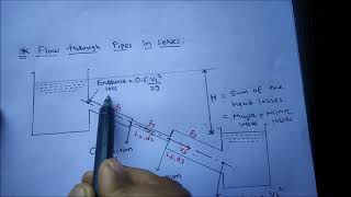
Three Reservoir Junction Problems
Chapter 3 of 4
🔒 Unlock Audio Chapter
Sign up and enroll to access the full audio experience
Chapter Content
Now if you look it the three reservoir junction problems which many of the time it is given that you have a multiple reservoirs okay. You may have the multiple water tanks are there and connected to the pipe flow systems and you have a junctions where you have three are connected here.
Detailed Explanation
These junction problems involve multiple reservoirs connected by pipes. In such configurations, the total inflow and outflow must balance at the junctions to maintain steady flow conditions. If we denote each flow from the reservoirs as Q1, Q2, and Q3, the mass continuity principle dictates that their combined flow rates must equal the flow that exits or enters the junction, which is necessary for the system to operate efficiently and without excess buildup or shortages in water.
Examples & Analogies
Picture this setup like three rivers meeting at a point. Each river flows at its own rate, and the combined flow into a larger body of water (like a lake) must match the sum of all the flows at the junction. If one river gets a flood and another dries up, the total must still remain balanced for the lake to maintain its water level.
Calculating Energy Losses
Chapter 4 of 4
🔒 Unlock Audio Chapter
Sign up and enroll to access the full audio experience
Chapter Content
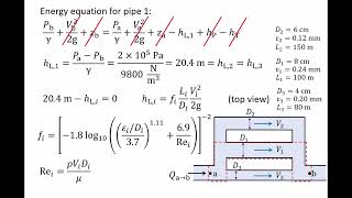
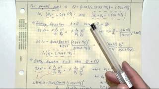
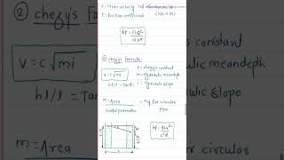
As is the parallel pipe flow you know these head losses of this path pipe 1 and pipe 2 should be equal. This is very simple; f is a constant and the head losses between either the pipe 1 or pipe 2 should be equal. Based on that you can compute what could be the d1, d2. Ratio is known to us. We have to compute the velocity ratio.
Detailed Explanation
In the context of parallel pipe flow, it's crucial to remember that any two pipes must exhibit equal head losses if the friction factors are constant across the system. This allows us to deduce mathematical relationships between the diameters and velocities of the flow within the pipes. Essentially, by setting the head losses equal to each other, we can derive formulas to calculate unknown variables such as diameters and velocities based on known factors.
Examples & Analogies
Imagine two water slides at a theme park that are designed to let water flow down them. If both slides are supposed to take the same amount of water (with the same frictional effects), then to ensure both slides work correctly, you might need to adjust their width and slope. By observing flow loss for both slides, you can calculate the required adjustments to maintain a balanced experience for the riders.
Key Concepts
-
Equal Energy Losses: Energy losses in parallel pipes must be equal to maintain flow balance.
-
Discharge Distribution: Total discharge remains constant among parallel pathways.
-
Head Loss Computation: Major and minor losses must be calculated to determine overall energy efficiency.
Examples & Applications
Example 1: Calculate the discharge in one of the parallel pipes given the diameter and friction factor while considering head loss.
Example 2: Analyze the energy losses in a three-pipe junction system to find the necessary hydraulic gradient.
Memory Aids
Interactive tools to help you remember key concepts
Rhymes
In pipes that parley, energy must tally—equal losses, for flow is our rally.
Stories
Imagine a festival where all paths must share the excitement equally—the more paths there are, the more careful we must be to ensure everyone enjoys the energy equally.
Memory Tools
Remember PEEL: Parallel paths equal energy loss.
Acronyms
HEAD
Hydraulic Energy And Discharge.
Flash Cards
Glossary
- Head Loss
The reduction in total mechanical energy of the fluid due to friction and other resistance characteristics in a pipe.
- Discharge (Q)
The volume of fluid per unit time passing through a cross-section of a pipe.
- Mass Conservation
The principle stating that mass cannot be created or destroyed in an isolated system; the total mass before a junction equals the total mass after.
- Hydraulic Gradient
A line that represents the potential energy head of fluid flow and indicates the energy level at different points in a pipe or natural flow.
- Minor Losses
Energy losses caused by fittings, changes in pipe diameter, and other factors that disrupt flow.
Reference links
Supplementary resources to enhance your learning experience.