
Example Problems
Enroll to start learning
You’ve not yet enrolled in this course. Please enroll for free to listen to audio lessons, classroom podcasts and take practice test.
Interactive Audio Lesson
Listen to a student-teacher conversation explaining the topic in a relatable way.
Velocity Defect Concept
🔒 Unlock Audio Lesson
Sign up and enroll to listen to this audio lesson

Today, we're starting with an important concept called the velocity defect. Can anyone tell me what they think that might mean?

Is it about how the flow velocity changes in different parts of the pipe?
Exactly! The velocity defect describes the difference in velocity from the average in turbulent flows. It’s crucial to understand how these defects occur as they impact flow behavior.

So how do we calculate it?
Good question! We often use dimensional analysis to relate velocity, depth in the fluid, and parameters like the pipe radius. Remember, this leads us to define an empirical constant, alpha, typically around 0.4 in many cases.

Why is that specific constant important?
It helps in modeling the average flow behavior in turbulent conditions, allowing engineers to predict flow patterns.
To recap, the velocity defect is essential for understanding real-world fluid dynamics—particularly in turbulent conditions where flow isn't uniform.
Pipes in Series
🔒 Unlock Audio Lesson
Sign up and enroll to listen to this audio lesson

Let’s move on to pipes in series. What do you think happens when fluid flows through multiple pipes connected one after the other?

I think the same amount of flow goes through each pipe, right?
Correct! The discharge remains constant across all pipes. However, we must consider energy losses too. Who remembers what kinds of losses we should account for?
Major losses due to friction and minor losses from changes in the pipe diameter?
That’s right! The total head loss can be a sum of these losses. It’s crucial for calculating the efficiency of a piping system.
So how do we find these losses?
For major losses, we use the Darcy-Weisbach equation, and minor losses can be calculated based on specific scenarios, such as bends or fittings in the piping. Let's summarize: in a series of pipes, the required flow remains consistent while accounting for both major and minor losses is essential.
Pipes in Parallel
🔒 Unlock Audio Lesson
Sign up and enroll to listen to this audio lesson
Next, we have pipes in parallel. Can someone explain what that entails?
Is it where multiple pipes carry fluid at the same time?
Exactly! In parallel configurations, the total energy losses across all paths must be equal, right? Why do you think that’s important?
Because it helps us understand how the flow divides among the pipes?
Exactly! We sum the discharges, and knowing that energy loss is equal from each path ensures we can analyze how energy translates into flow distribution within each branch.
So we can think of it like splitting a single road into multiple lanes?
Very good analogy! Now, let’s recap: total energy loss across all paths is equal, and the discharge splits while maintaining energy conservation principles.
Three Reservoir Junction Problem
🔒 Unlock Audio Lesson
Sign up and enroll to listen to this audio lesson
Now, let's tackle a more complex scenario—the three-reservoir junction. What do we need to consider here?
The conservation of mass and energy, right?
Correct! At the junction, total outflow must equal inflow, which means we can apply the continuity equation. What about hydraulic gradients?
We have to account for the height differences between the reservoirs and the energy losses?
Exactly! This affects how we calculate the heads at each reservoir. The energy gradient line should remain consistent, which roots back to the energy loss computations we've learned.
So, we equate energy losses to solve for flows at each reservoir?
That's right! In summary, knowing how to approach flow at junctions helps to maintain effective and efficient systems.
Introduction & Overview
Read summaries of the section's main ideas at different levels of detail.
Quick Overview
Standard
In this section, we explore key concepts related to fluid dynamics in pipe systems, including velocity defect laws, head losses in series and parallel pipes, and analytical approaches to reservoir junction problems. Practical examples reinforce these concepts, allowing for a deeper understanding through calculations and applications.
Detailed
Example Problems
In this section, we provide an in-depth look at fluid dynamics within pipe systems. The discussion begins with the concept of velocity defects, which focuses on the deviations of velocity from average velocity in turbulent flow conditions. We introduce significant principles derived from dimensional analysis, especially regarding average and shear velocities indicated by an empirical constant, alpha, with an experimental value of 0.4.
Following this introduction, we examine the characteristics of pipes in series. Just like in electric circuits, fluid flow in a series is characterized by equal discharge across all pipes; however, energy losses—both major (due to friction) and minor (due to changes in diameter, expansions, contractions, etc.)—must be carefully calculated to determine total head loss. The section progresses to pipes in parallel, which require a similar analysis where the energy losses must be equal across the branches of flow.
An important concept introduced is the three-reservoir junction problem, emphasizing mass conservation where the total discharge at a junction equals zero, allowing for calculations of hydraulic gradients and heads.
Finally, several practical examples, including GATE examination problems, serve as illustrative cases to consolidate understanding of the concepts of energy losses and flow rates in both simple and complex systems.
Youtube Videos


Audio Book
Dive deep into the subject with an immersive audiobook experience.
Introduction to Pipe Systems
Chapter 1 of 7
🔒 Unlock Audio Chapter
Sign up and enroll to access the full audio experience
Chapter Content
Now we coming back to the very simple examples okay. And that is what is in your text book is necessary to for. If you look it that, many of the times you have the pipes in series, pipes in parallel or three reservoir junction problems okay.
Detailed Explanation
This chunk introduces the topic of pipe systems, emphasizing that this section will cover fundamental problems such as pipes arranged in series and parallel, as well as junctions involving multiple reservoirs. Understanding these basic configurations is key to solving more complex fluid flow problems.
Examples & Analogies
Think of water flowing in a system like electricity flowing through wires. Just as wires can be connected in series or parallel, pipes can also be arranged in these configurations, affecting how water flows and how much pressure is lost.
Pipes in Series
Chapter 2 of 7
🔒 Unlock Audio Chapter
Sign up and enroll to access the full audio experience
Chapter Content
If you have definitely the discharge will be for a steady state conditions for steady flow conditions. So discharge at the Q1, Q2, Q3 that should be equal because this is a steady state. Q1 = Q2 = Q3 = constant.
Detailed Explanation
In a series configuration, the discharge (the volume of fluid flowing per unit time) must remain constant across all pipes. This is because in a steady flow condition, what enters one section must exit. Therefore, if three pipes are connected in series, the amount of fluid passing through each must be the same.
Examples & Analogies
Imagine a line of people passing buckets of water down a chain. Each person only passes along what they've received, so the same amount flows along the entire line. If one person tries to hold back the water, it affects everyone at the chain.
Calculating Energy Losses in Series Pipes
Chapter 3 of 7
🔒 Unlock Audio Chapter
Sign up and enroll to access the full audio experience
Chapter Content
But when you have a pipe in series please remember it that you always should consider whether there is a minor losses. There is major losses which is the frictional losses component for the pipe 1. Also there will be a minor losses because the change of the diameter of the pipe okay there will be expansion or the contraction exit loss, entry losses all the loss component you have to look it which way the flow is happening it.
Detailed Explanation
In a series of pipes, both major and minor losses must be taken into account when calculating the total energy loss. Major losses are typically due to friction along the pipe's length, while minor losses arise from factors like changes in diameter (expansion or contraction), as well as entry and exit points.
Examples & Analogies
Think of a water slide. As water flows down, friction against the slide's surface causes energy loss (major losses). If the slide suddenly widens or narrows at any point, it causes a splash (minor losses). Understanding both helps ensure a smooth ride.
Pipes in Parallel
Chapter 4 of 7
🔒 Unlock Audio Chapter
Sign up and enroll to access the full audio experience
Chapter Content
When you have a pipe in a parallels, you can understand it see if I have the pipe in the parallels, there are three pipes are connected here. This is the A is entry point, B is exit point. From the this point to this point the total energy losses passing through this path A or path B or path C that should be equal.
Detailed Explanation
In parallel pipe systems, the total energy loss must be the same for all paths leading from A (entry) to B (exit). Regardless of which path the flow takes, the energy used to overcome friction and other losses should balance out. This is crucial for ensuring proper fluid distribution through the system.
Examples & Analogies
Consider multiple roads leading to the same destination. Even if one road is longer than another, each driver (fluid) uses energy (gasoline) to travel this distance. If one path has more bumps (friction), it will use more energy, but the total energy used must balance out across all paths.
Three Reservoir Junction Problems
Chapter 5 of 7
🔒 Unlock Audio Chapter
Sign up and enroll to access the full audio experience
Chapter Content
Now if you look it the three reservoir junction problems which many of the time it is given that you have a multiple reservoirs okay. You may have the multiple water tanks are there and connected to the pipe flow systems and you have a junctions where you have three are connected here.
Detailed Explanation
In problems involving three reservoirs, you may need to consider how water flows between them and what flow rates are necessary to maintain balance. At the junction, the law of conservation of mass applies, meaning the total discharge must equate to the sum of inflows and outflows.
Examples & Analogies
Imagine three buckets with holes in them. If you pour water into one bucket, it will flow through the holes into the other buckets. The rate at which water flows into each bucket must balance out so they all maintain a certain level.
Applying Energy Loss Calculations
Chapter 6 of 7
🔒 Unlock Audio Chapter
Sign up and enroll to access the full audio experience
Chapter Content
So you have a three equations as well as this equations help us to find out the flow directions and the head losses of a three reservoir junctions problems okay.
Detailed Explanation
The equations derived from the conservation of mass and energy principles help in calculating flow directions and energy losses in systems involving multiple reservoirs. By knowing the input and output, we can solve for unknowns in the flow.
Examples & Analogies
Think of a system of rivers flowing into a lake where the inflow must match the outflow. Measuring the heights of water in different spots (head) helps determine how much water is entering or leaving the lake at any given time.
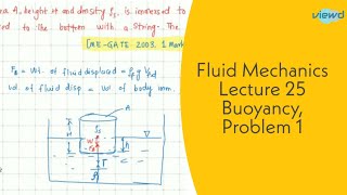
Example Problem from GATE 2014
Chapter 7 of 7
🔒 Unlock Audio Chapter
Sign up and enroll to access the full audio experience
Chapter Content
An incompressible fluid flowing through a steady rate in a horizontal pipe, okay. From a section, pipe is divided into two horizontal pipes as given the d1 and d2 okay and d1 is four times of d2 run for a distance l each other.
Detailed Explanation
This problem illustrates the application of prior knowledge about fluid dynamics, specifically how to calculate flow characteristics when a single pipeline splits into two parallel pipes of different diameters. The tasks include determining the flow velocities and head losses in each pipe.
Examples & Analogies
Imagine a garden hose that splits into two smaller hoses. If one hose is much wider than the other, the water will flow differently through each. By analyzing how much water is coming out of each hose, we can understand how efficiently the system works.
Key Concepts
-
Velocity Defect: A measure of how local velocities vary from the average flow in turbulent conditions.
-
Head Loss: The energy lost due to friction and other factors in piping systems.
-
Pipes in Series: A configuration where fluid flows through multiple pipes sequentially, and total energy loss is a sum of individual losses.
-
Pipes in Parallel: Configured such that multiple pipes share the same inlet and outlet, requiring equal energy losses across the paths.
-
Hydraulic Gradient: Indicator of the energy per unit weight of fluid that affects flow within a piping system.
Examples & Applications
In a series of three pipes connected in a row, if pipe 1 has a major loss of 3m and pipe 2 has 2m, and pipe 3 has 1m, the total loss is 6m.
In a parallel arrangement, if one branch experiences 2m of head loss while the other experiences 3m, the efficiency of flow can be analyzed based on equal energy losses.
Memory Aids
Interactive tools to help you remember key concepts
Rhymes
In series we add, in parallel we balance, energy losses we never take for granted.
Stories
Imagine a race where cars line up on three tracks (pipes in series), each taking a bit of energy, then they regroup, maintaining the flow without losing strength (parallel).
Memory Tools
SPLASH: Series = Sum of losses, Parallel = Equal losses.
Acronyms
HEAD
Head loss Equals the Aggregate of Deviations.
Flash Cards
Glossary
- Velocity Defect
The difference between average velocity and local flow velocity in turbulent flow conditions.
- Head Loss
The reduction in total mechanical energy of the fluid as it moves through a pipe due to friction and other energy losses.
- Major Losses
Energy losses in fluid flow primarily due to friction within pipes.
- Minor Losses
Energy losses caused by fittings, valves, and other changes in diameter or flow direction.
- Hydraulic Gradient
The slope of the energy line in a hydraulic system that indicates how fluid moves from one point to another.
Reference links
Supplementary resources to enhance your learning experience.