
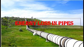
Energy Losses in Pipes
Enroll to start learning
You’ve not yet enrolled in this course. Please enroll for free to listen to audio lessons, classroom podcasts and take practice test.
Interactive Audio Lesson
Listen to a student-teacher conversation explaining the topic in a relatable way.
Introduction to Energy Losses
🔒 Unlock Audio Lesson
Sign up and enroll to listen to this audio lesson

Today, we are going to learn about energy losses in pipes, primarily focusing on losses due to friction and other factors. When fluid flows through a pipe, it doesn't flow perfectly; there are always energy losses. Who can guess why?

Is it because of friction with the pipe walls?
Exactly! That's called major losses. We also have minor losses due to fittings and changes in pipe diameter. Let's remember the acronym 'ME' for Major and Minor Energy losses. Can anyone think of examples for minor losses?

What about bends in the pipes or valves?
Yes, great examples! Bends and valves create turbulence, increasing energy loss. Now let's see how we can quantify these losses.
Calculating Major Losses
🔒 Unlock Audio Lesson
Sign up and enroll to listen to this audio lesson

To calculate major losses, we typically use the Darcy-Weisbach formula. Can someone tell me what factors we need for this calculation?

We need the length of the pipe, diameter, flow velocity, and the friction factor.
Correct! And the friction factor can depend on whether the flow is laminar or turbulent. Just for memory, let's use 'FLVD' to remember: Friction, Length, Velocity, Diameter. How would you identify if the flow is laminar or turbulent?

Using the Reynolds number!
Exactly! Remember that a Reynolds number below 2000 indicates laminar flow. Now, let's discuss how to apply these principles to real-world examples.
Pipes in Series
🔒 Unlock Audio Lesson
Sign up and enroll to listen to this audio lesson
Now let's consider pipes in series. When we have multiple pipes connected end to end, what happens to the total head loss?
The total head loss is the sum of the losses in each pipe.
Correct! If we denote the head losses as Δh1, Δh2, and so on, then the total head loss Δh is Δh1 + Δh2. Remember this equation for your calculations. What about minor losses in series?
Do we include those too?
Yes! Always consider both major and minor losses. Let’s work through an example after this discussion.
Pipes in Parallel
🔒 Unlock Audio Lesson
Sign up and enroll to listen to this audio lesson
Next, we'll explore pipes in parallel. In this case, what do you think happens to the energy losses?
Each path has to have equal energy losses for the total flow to remain consistent?
Exactly! That's essential in understanding parallel flows. Remember the phrase 'Equal Energy, Equal Loss' to maintain clarity. How might this affect flow distribution?
I guess it would mean we need to account for the relative sizes of the pipes, right?
Correct! The diameter differences in the pipes will affect the flow rate and energy losses. This is a critical factor when designing systems.
Three Reservoir Junctions
🔒 Unlock Audio Lesson
Sign up and enroll to listen to this audio lesson
Finally, let’s discuss three reservoir junctions. What happens at these points?
The flow could be entering or leaving, and we need to maintain mass and energy conservation.
Exactly! We use the conservation equations to determine flow directions. Who can tell me what kind of losses we need to compute?
We would consider the head losses due to friction plus any minor losses.
Absolutely! This is vital for maintaining proper flow. Remember our earlier discussions about hydraulic gradients, as they will apply here too. Now, let's summarize the key concepts we've covered today!
Introduction & Overview
Read summaries of the section's main ideas at different levels of detail.
Quick Overview
Standard
The section elaborates on energy losses in pipes caused by friction and other factors, introducing concepts like velocity defects, major and minor losses, and their impact on steady flow conditions. It covers pipe configurations such as series and parallel connections, providing a foundation for calculating energy losses in practical applications.
Detailed
Energy Losses in Pipes
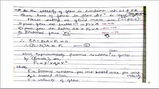
This section focuses on the losses of energy as fluid travels through pipes, an essential concept in fluid mechanics and engineering applications. Energy losses primarily arise from frictional forces and they impact the efficiency of flow in various configurations of pipes. The discussion begins with the introduction of the velocity defect concept, which measures deviations from average fluid velocity. This can be represented mathematically through dimensional analysis.
Further, the section highlights experimental findings from historical studies, notably the Nikuradse experiments, which determine the coefficients that characterize energy losses in turbulent flow.
Key concepts include:
- Major Losses: Primarily due to friction between the fluid and the pipe walls, which depends on the flow characteristics and pipe material.
- Minor Losses: Resulting from sudden changes in flow areas, bends, or fittings that disrupt smooth flow and add additional head loss.
- Pipe Configurations: Two main configurations are discussed:
- Pipes in Series: Where total head loss is the sum of individual pipe losses, including both major and minor losses.
- Pipes in Parallel: Where multiple pathways allow fluid to split and divert, necessitating the equality of energy losses across all incoming paths.
- Three Reservoir Junction Problems: Illustrating how mass and energy conservation principles apply in complex flow systems with junctions, informing the hydraulic gradients necessary to sustain flow between reservoirs.
These principles are explored with practical examples, guiding calculations for head loss due to frictional forces and giving students tools for problem-solving in real-world scenarios.
Youtube Videos


Audio Book
Dive deep into the subject with an immersive audiobook experience.
Velocity Defect Concept
Chapter 1 of 5
🔒 Unlock Audio Chapter
Sign up and enroll to access the full audio experience
Chapter Content
But if you go to the outer layers where we look it that a velocity defect concept, how far the velocity from average velocity, that the defect means how much deviations how much difference between that. If you look it that and looking... (Refer Slide Time: 27:31)
Detailed Explanation
In fluid dynamics, especially in the context of pipes, the term 'velocity defect' refers to how much the velocity of the fluid deviates from the average velocity. In other words, it's a measure of how smoothly the fluid is flowing. In the outer layers of fluid flow, where turbulence is present, we notice significant differences in the velocity of the fluid compared to the average. Understanding this concept is crucial as it allows engineers to predict flow patterns and potential energy losses in pipes due to turbulence.
Examples & Analogies
Consider a group of runners in a race. If most runners average around 10 km/h, but some runners are sprinting at 15 km/h while others jog at 5 km/h, the discrepancies between these speeds represent their 'velocity defects' compared to the average. Just like the runners, fluid particles in a pipe move at different speeds, impacting the overall efficiency and energy loss in the system.
Understanding Energy Loss in Series Pipes
Chapter 2 of 5
🔒 Unlock Audio Chapter
Sign up and enroll to access the full audio experience
Chapter Content
Many of the times you have the pipes in series, pipes in parallel or three reservoir junction problems. Pipe in series is a very simple problems like electric circuits, okay. You can have a series of wires you have from point A to B. If you have definitely the discharge will be for a steady state conditions for steady flow conditions. So discharge at the Q1, Q2, Q3 that should be equal because this is a steady state.
Detailed Explanation
When considering pipes arranged in series, the concept is analogous to an electrical circuit where current flows through a series of resistors. In hydraulic systems, as water flows through successive pipes, the discharge (or flow rate) remains constant provided the conditions are steady. However, energy losses occur due to friction and other factors, and the total head loss in a series of pipes is the sum of the head losses for each individual pipe.
Examples & Analogies
Imagine a long slide at a playground that consists of several segments. As children slide down each segment, they might slow down due to friction with the surface. Regardless of how many segments there are, if one child starts at the top, the same amount of energy is required to reach the bottom—albeit distributed among all segments, similar to water flowing through pipes.
Major and Minor Losses in Pipes
Chapter 3 of 5
🔒 Unlock Audio Chapter
Sign up and enroll to access the full audio experience
Chapter Content
But when you have a pipe in a series please remember it that you always should consider whether there are minor losses. There is major losses which is the frictional losses component for the pipe 1. Also there will be a minor losses because the change of the diameter of the pipe, okay there will be expansion or the contraction exit loss, entry losses all the loss component...
Detailed Explanation
Energy losses in pipe systems can be categorized into major and minor losses. Major losses are primarily due to friction as fluid moves through the pipe's length, while minor losses occur at junctions, bends, and changes in diameter. Both types of losses must be accounted for in calculations to ensure an accurate assessment of the total energy losses experienced by the fluid.
Examples & Analogies
Think of driving a car on a winding road. The friction between the tires and road represents major losses as you drive straight. However, every time you make a turn or go up a hill, you have to exert extra effort, which corresponds to minor losses. Understanding both helps you gauge how much energy is used on your journey.
Energy Loss Calculations in Series and Parallel Pipes
Chapter 4 of 5
🔒 Unlock Audio Chapter
Sign up and enroll to access the full audio experience
Chapter Content
Now if you look at another very simple problems that pipes in parallel. When you have a pipe in parallels, you can understand it see if I have the pipe in the parallels, there are three pipes are connected here. This is the A is entry point, B is exit point... (Refer Slide Time: 32:05)
Detailed Explanation
In parallel pipe systems, fluid can take multiple paths through different pipes, and energy losses are equal across all paths. The overall flow is separated among these pipes, but regardless of the route chosen, the sum total of energy losses remains constant. This property is essential for ensuring that systems can manage flow effectively and maintain required pressures.
Examples & Analogies
Picture a busy street where traffic can either take the left lane or the right lane at an intersection. Although cars may split between the two lanes, the total number of cars entering and leaving the intersection remains the same. Similarly, in parallel pipes, while the flow can divide, the energy required to maintain that flow stays equal overall.
Three Reservoir Junction Problems
Chapter 5 of 5
🔒 Unlock Audio Chapter
Sign up and enroll to access the full audio experience
Chapter Content
Now we are coming back to the very simple examples okay. And that is what is in your textbook is necessary to for. If you look at these three flow one could be also outflow...
Detailed Explanation
In a three reservoir junction problem, multiple reservoirs connect through pipes, and the flow direction can vary based on demand. The principle of conservation of mass applies, meaning the total incoming flow equals the outgoing flow. Additionally, it becomes essential to calculate how much energy loss occurs at junctions, helping to plan effective routing of fluid to maintain necessary pressure throughout the system.
Examples & Analogies
Imagine a water park where three slides converge into a single pool. Water from each slide must flow into the pool without overflowing. The balance—the amount coming from each slide must equal what flows out—is crucial for efficient operation. Similarly, engineers analyze flow rates and energy losses at junctions to ensure proper water management.
Key Concepts
-
Velocity Defect: The difference between actual fluid velocity and average fluid velocity.
-
Head Loss: The loss of energy in the fluid due to friction and turbulence.
-
Series and Parallel Pipes: Different configurations affecting energy losses in flow systems.
Examples & Applications
For a pipe in series, if Pipe 1 has a head loss of 2 meters and Pipe 2 has a head loss of 3 meters, the total head loss is 5 meters.
In a three-reservoir system, flows entering and leaving must equal zero at the junction based on conservation principles.
Memory Aids
Interactive tools to help you remember key concepts
Rhymes
Energy loss comes from friction, minor losses add to the contradiction.
Stories
Imagine a water slide (pipe) where friction slows down the fun (flow), plus bumps and turns (minor losses) make it even more tricky!
Memory Tools
Remember 'ME' for Major and Minor energy losses.
Acronyms
FLVD - Friction, Length, Velocity, Diameter for key factors in major losses.
Flash Cards
Glossary
- Energy Losses
Reduction in usable energy of a fluid due to friction and turbulence as it flows through pipes.
- Major Losses
Energy losses primarily due to friction between the fluid and pipe walls.
- Minor Losses
Energy losses caused by fittings, bends, and other disruptions to fluid flow.
- Reynolds Number
Dimensionless number used to predict flow regime; indicates whether flow is laminar or turbulent.
- DarcyWeisbach Formula
Formula used to calculate major energy losses in a flowing fluid due to friction.
- Flow Rate (Q)
Volume of fluid that passes through a given surface per unit of time.
Reference links
Supplementary resources to enhance your learning experience.