
Flow Distribution in Parallel Pipes
Enroll to start learning
You’ve not yet enrolled in this course. Please enroll for free to listen to audio lessons, classroom podcasts and take practice test.
Interactive Audio Lesson
Listen to a student-teacher conversation explaining the topic in a relatable way.
Introduction to Flow in Pipes
🔒 Unlock Audio Lesson
Sign up and enroll to listen to this audio lesson

Today, we will learn about how fluid flows in parallel pipes. Can anyone tell me what happens when fluid meets a junction?

The flow splits into different paths?
Exactly! When fluid flows through parallel pipes, it divides among the different paths based on various factors like diameter and friction. Now, who can explain what velocity defect means?

Is it the difference between the actual velocity and the average velocity?
Spot on! The velocity defect helps us understand how flow is affected by turbulence. Remember, higher turbulence means greater velocity defects. Can anyone give me an example of where we might see this in real life?

I think it would happen in rivers where the flow is not uniform.
Great example! Let’s summarize today’s key points: The flow splits in parallel pipes, velocity defects indicate differences in flow, and turbulence affects these velocities.
Energy Losses in Pipelines
🔒 Unlock Audio Lesson
Sign up and enroll to listen to this audio lesson

Now, let's discuss energy losses in parallel pipes. What types of losses can occur in this context?

I think there are major losses from friction and minor losses from other factors.
Correct! Major losses are primarily due to friction in the pipes, while minor losses occur from factors such as bends, fittings, or changes in pipe diameter. What is the first thing we need to calculate these losses?
We need the Darcy-Weisbach equation to find the friction loss.
Right! The Darcy-Weisbach equation allows us to compute the head loss due to friction efficiently. Let’s recap: Energy losses can be major or minor, and both contribute to our overall hydraulic system performance.
Application of Concepts
🔒 Unlock Audio Lesson
Sign up and enroll to listen to this audio lesson
Let’s put our theories to practice. Imagine we have two parallel pipes with different diameters. If the discharge is constant, what can we say about the relationship of the velocities in these pipes?
If one pipe is larger, its velocity would be lower to maintain the same discharge!
Excellent! This is a foundational principle of fluid dynamics. In fact, the ratio of the velocities can be expressed mathematically. Let’s work through a problem to demonstrate this.
Are there formulas we can use to do that?
Absolutely! By equating the head losses in both pipes using the Darcy-Weisbach equation, we can find the velocity ratio based on their diameters. Remember, practical application of these equations is critical in engineering design.
Junction and Discharge Problems
🔒 Unlock Audio Lesson
Sign up and enroll to listen to this audio lesson
Next, we will tackle junction problems. Can anyone tell me what happens at a junction where multiple pipes converge?
The total inflow needs to equal the outflow at that junction!
Exactly! This is known as the principle of continuity. If we say that the sum of all inflows equals the sum of all outflows, how can we express this mathematically given different velocities?
We can use the equation Q1 + Q2 + Q3 = 0 to illustrate this.
Well articulated! Let’s also remember that the energy losses should be equal across all paths, so we can calculate discharge in differing paths based on energy losses.
Introduction & Overview
Read summaries of the section's main ideas at different levels of detail.
Quick Overview
Standard
The section elaborates on how flow is distributed in parallel pipes and the significance of velocity defects. It details energy losses occurring in such systems due to friction and minor losses, and explains the application of these principles through examples and equations related to discharge in parallel configurations.
Detailed
Flow Distribution in Parallel Pipes
In this section, we explore the distribution of flow in parallel pipes, focusing on the concept of velocity defects, which represents the deviation of the actual velocity from the average velocity. The analysis begins with the examination of dimensional equations that describe the relationship between flow velocity and critical parameters such as pipe radius and turbulence flow.
Key Concepts Covered:
- Velocity Defect: A measure of how much the velocity deviates from the average velocity in the flow.
- Energy Losses: In pipe systems, the energy loss due to friction and other minor losses is crucial to calculating the efficiency of flow.
- Parallel Pipes: When discussing systems of pipes connected in parallel, the section examines how flow divides among the lanes, observing that energy losses must remain equal across all paths so that mass conservation is maintained.
The section provides illustrative examples, including the analysis of three-reservoir junction issues and case studies on the velocity ratios in different-sized pipes, highlighting the application of Darcy-Weisbach formulae in practical calculations. In essence, understanding flow distribution in parallel pipes is vital for hydraulic system design and efficiency.
Youtube Videos


Audio Book
Dive deep into the subject with an immersive audiobook experience.
Introduction to Flow Distribution
Chapter 1 of 6
🔒 Unlock Audio Chapter
Sign up and enroll to access the full audio experience
Chapter Content
If you look it at, many of the times you have the pipes in series, pipes in parallel or three reservoir junction problems. Pipe in series is a very simple problems like electric circuits, okay. You can have a series of wires you have from point A to B.
Detailed Explanation
In fluid dynamics, we often analyze how fluids flow through pipes that can be arranged in series or parallel. Series pipes can be compared to electrical circuit components connected one after another. When fluid flows through such pipes, the total flow rate remains constant because the same amount of fluid flows through every segment of the series. This concept is foundational for understanding how fluids behave in different configurations.
Examples & Analogies
Imagine a water slide at an amusement park. If you have multiple slides in a row (like pipes in series), water flows through each slide one after the other. Regardless of how many slides there are, the amount of water entering the first slide equals the amount exiting the last slide.
Understanding Head Loss in Series Pipes
Chapter 2 of 6
🔒 Unlock Audio Chapter
Sign up and enroll to access the full audio experience
Chapter Content
If you have definitely the discharge will be for a steady state conditions for steady flow conditions. So discharge at the Q1, Q2, Q3 that should be equal because this is a steady state.
Detailed Explanation
In parallel pipe systems, the flow rates across each parallel path must balance due to the law of conservation of mass. This means that the total discharge entering the system (Q1 + Q2 + Q3) must equal the total discharge leaving. It’s important to understand that while the flow rates can be different depending on the pipe configurations, at steady state, the sum of discharges must remain constant.
Examples & Analogies
Think of a highway with multiple lanes. If 100 cars (representing total flow) enter the highway, they can spread across the lanes. Some lanes may have more cars than others (like varying flow rates in different pipes), but the total number of cars still adds up to 100 as they exit the highway.
Energy Loss Considerations
Chapter 3 of 6
🔒 Unlock Audio Chapter
Sign up and enroll to access the full audio experience
Chapter Content
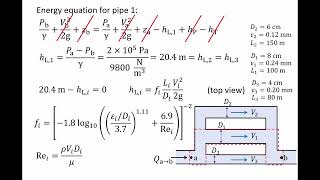
But when you have a pipe in series, please remember that you always should consider whether there are minor losses. There are major losses which is the frictional losses component for the pipe 1.
Detailed Explanation
When analyzing flow through pipes, it's critical to consider energy losses that occur due to friction as the fluid moves through the pipe. Major losses primarily come from the frictional resistance of the pipe wall, while minor losses can occur from bends, fittings, and changes in diameter. These losses affect the efficiency of the system and must be calculated to ensure sufficient energy remains for fluid movement.
Examples & Analogies
Imagine trying to slide down a long slide covered in rough material. You will slow down significantly because of friction (major loss). Now, if the slide also has bumps and turns (minor losses), it becomes even harder to slide down quickly. Similarly, in a pipe, both friction and configuration contribute to energy loss during fluid flow.
Flow Distribution in Parallel Pipe Systems
Chapter 4 of 6
🔒 Unlock Audio Chapter
Sign up and enroll to access the full audio experience
Chapter Content
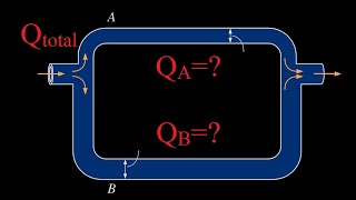
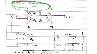
When you have a pipe in parallel, you can understand it see if I have the pipe in parallels, there are three pipes connected here. This is the A is entry point, B is exit point.
Detailed Explanation
In parallel piping systems, multiple pathways exist for fluid to flow from the entry point (A) to the exit point (B). The flow gets divided among the different pipes based on their diameter, length, and the friction losses encountered in each. Although the total flow rate remains constant, the individual discharge through each pipe may vary. All paths will experience the same total energy losses to maintain hydraulic balance.
Examples & Analogies
Consider a group of friends entering a restaurant through multiple doors (parallel pipes). Depending on which doors are open and how wide they are, people may choose different paths to go inside. However, no matter the route taken, the total number of people inside will always match the number that entered no matter which door they picked.
Energy Loss Equilibrium
Chapter 5 of 6
🔒 Unlock Audio Chapter
Sign up and enroll to access the full audio experience
Chapter Content
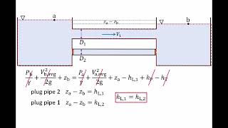
As the flow is coming and divide into three parts, we can always write the Q what is coming will be distributed into the three parts in this figure. So as you have a branching out, as you are converging it, you can write the total energy losses should be equal.
Detailed Explanation
For energy conservation to hold true in a parallel system, the total energy loss across each individual pipe must be equivalent. That means if one pipe has a more significant friction loss, it’s balanced by a lower loss in another pipe, ensuring that fluid can exit (and enter) efficiently without pressure buildup or backflow.
Examples & Analogies
Imagine three siblings sharing a pool of marbles (the energy). Depending on how you partition the marbles between them (the pipes), they can still distribute them evenly such that no one is left without enough (no pressure buildup). Despite how the marbles are divided, the total remains consistent, showing balance among their pathways.
Three Reservoir Junction Problems
Chapter 6 of 6
🔒 Unlock Audio Chapter
Sign up and enroll to access the full audio experience
Chapter Content
Now if you look at the three reservoir junction problems which many of the time it is given that you have multiple reservoirs.
Detailed Explanation
In hydraulic systems containing multiple reservoirs connected by pipes, these 'junctions' become vital control points. The flow into and out of these junctions needs to be assessed to maintain balance in fluid distribution. Using principles of conservation of mass helps determine the flow directions and quantify energy losses across different paths to and from the junctions.
Examples & Analogies
Consider a roundabout where cars enter and exit from various roads (the junction). Depending on traffic flow, cars need to maintain balance—if too many cars enter one road too quickly, the flow can get jammed. Similarly, in a junction problem, ensuring the right amount of fluid flows to and from each reservoir helps prevent backups and maintains smooth operation.
Key Concepts
-
Velocity Defect: The difference from average velocity in fluid flow.
-
Energy Losses: Losses in hydraulic systems due to friction and fittings.
-
Paraell Pipes: Understanding flow distribution through multiple pathways.
-
Head Loss: The decrease in energy as fluid flows through pipes.
Examples & Applications
When water flows through a larger pipe and a smaller pipe in parallel, the small pipe will have a higher velocity than the larger one to maintain constant discharge.
In a junction with three pipes, the sum of all inflows equals the sum of all outflows, highlighting the importance of mass conservation.
Memory Aids
Interactive tools to help you remember key concepts
Rhymes
In pipes where waters race, / The flow divides with steady pace, / Major losses slow it down, / Minor bends can make it frown.
Stories
Once upon a time, in Waterland, pipes of various sizes flowed together. Each pipe had its own speed, but they all needed to meet at the junction without losing energy. The wise engineer knew that he must calculate the friction losses to make sure that all was fair in flow.
Memory Tools
Remember PEM: Pipes Energy Major losses! It helps you recall the types of energy loss: friction (Major) and minor (bends/junctions).
Acronyms
FLAME
Friction
Losses
Average
Major
Energy. Use it to remember the key concepts of energy loss in pipes.
Flash Cards
Glossary
- Velocity Defect
The difference in speed of fluid compared to its average velocity, often influenced by turbulence.
- Energy Losses
Reductions in energy caused by friction and other factors in hydraulic systems.
- DarcyWeisbach Equation
An equation used to calculate pressure loss due to friction in a pipe.
- Head Loss
The reduction in total mechanical energy of a fluid as it moves through a hydraulic system.
- Minor Losses
Energy losses in hydraulic systems caused by fittings, bends, junctions, and other non-linear features.
Reference links
Supplementary resources to enhance your learning experience.