
Examples in Pipe Systems
Enroll to start learning
You’ve not yet enrolled in this course. Please enroll for free to listen to audio lessons, classroom podcasts and take practice test.
Interactive Audio Lesson
Listen to a student-teacher conversation explaining the topic in a relatable way.
Understanding Velocity Defects
🔒 Unlock Audio Lesson
Sign up and enroll to listen to this audio lesson

Today we're going to discuss the velocity defect concept. Can anyone tell me what velocity defect refers to?

Is it about the difference between actual velocity and average velocity?
Exactly! The velocity defect measures how much instantaneous velocity deviates from the average velocity in pipe flows, particularly in turbulent conditions.

How does this relate to pipe radius?
Good question! When analyzing high turbulence flow, we can replace height with the pipe radius, allowing us to understand how velocity changes across the pipe.
Now, let’s summarize. The velocity defect reveals differences between instantaneous and average velocities, especially important in turbulent flows.
Energy Losses in Pipe Systems
🔒 Unlock Audio Lesson
Sign up and enroll to listen to this audio lesson

Next, let's discuss energy losses in pipes. Can anyone explain what major and minor losses are?

I think major losses are from friction along the pipe, and minor losses happen at bends or changes in diameter?
Correct! Major losses are primarily due to friction while minor losses arise from fittings, bends, or changes in diameter.

How can we calculate total head loss in a system?
In pipes connected in series, you sum the head losses of each section together, including both major and minor losses. Always analyze the flow conditions carefully!
So to recap, major losses are frictional, while minor losses occur at fittings and transitions. Total head loss is the sum of all.
Pipe Configurations: Series vs. Parallel
🔒 Unlock Audio Lesson
Sign up and enroll to listen to this audio lesson
Now let's shift to pipe configurations. Who can tell me the main difference between series and parallel pipes?
In series, the flow goes through one pipe at a time, while in parallel, it can divide among several pipes.
That's right! In series, the discharge remains constant while you add head losses. In parallel systems, energy losses in each pipe need to be equal.
What about flow junctions with multiple reservoirs?
Excellent point! At junctions, the flow from multiple pipes combines and must maintain mass balance. The total flow should equal the combined inputs minus any outflows.
To summarize, series pipes have a constant discharge but different head losses, while parallel pipes require equal energy losses across all branches.
Application of Concepts – Solving Problems
🔒 Unlock Audio Lesson
Sign up and enroll to listen to this audio lesson
Finally, let’s apply what we learned by solving real-life problems. What’s the first step in approaching a pipe flow problem?
We should sketch the problem first for better understanding.
Exactly! Then identify all known variables like diameters, flow rates, and friction factors.
How do we handle multiple pipes in series or parallel?
In those cases, calculate head losses for each pipe, accounting for both major and minor losses, and follow through with the continuity equations.
To recap, sketching helps design the approach, and analyzing head losses is crucial to determining flow characteristics.
Introduction & Overview
Read summaries of the section's main ideas at different levels of detail.
Quick Overview
Standard
In this section, we delve into the fundamentals of pipe systems, discussing important concepts such as velocity defects, energy losses, and different pipe configurations like series and parallel arrangements. We also cover practical application problems to consolidate understanding.
Detailed
Detailed Summary
This section focuses on the fundamental concepts of pipe systems and their associated behaviors. It begins by analyzing velocity profiles, particularly the velocity defect concept, which explains deviations between average and instantaneous velocities. The discussion extends to dimensional analysis derived from experimental findings, including the Nikuradse experiment, and covers the implications of high turbulence flow.
The section progresses to present various pipe configurations such as pipe systems in series and parallel. For pipes in series, the text highlights how steady-state conditions result in constant discharge, considering both major and minor energy losses that occur along the flow path.
Parallel pipe systems are also explored, emphasizing that energy losses must be equated regardless of the flow path taken. We examine three reservoir junction problems, which demonstrate continuity equations and hydraulic gradients. The exploration of these concepts is reinforced with examples drawn from problems like the GATE examination, illustrating real-world applications and methodologies in managing and predicting flow behavior through pipe systems.
Youtube Videos


Audio Book
Dive deep into the subject with an immersive audiobook experience.
Introduction to Pipe Systems
Chapter 1 of 6
🔒 Unlock Audio Chapter
Sign up and enroll to access the full audio experience
Chapter Content
Now we coming back to the very simple examples okay. And that is what is in your text book is necessary to for. If you look it that, many of the times you have the pipes in series, pipes in parallel or three reservoir junction problems okay.
Detailed Explanation
In this part, we introduce the basic setups encountered in pipe systems. We differentiate between series and parallel configurations and also mention the relevance of three-reservoir junction problems. Series pipes are similar to how current flows through a single path in electrical circuits, while parallel pipes have multiple paths through which fluid can flow.
Examples & Analogies
Think of a water slide at a water park. If you have one slide after another (series), all water goes through each slide one after another. But if you have multiple slides that can be taken at the same time (parallel), the water can choose any slide to descend.
Pipe in Series Configurations
Chapter 2 of 6
🔒 Unlock Audio Chapter
Sign up and enroll to access the full audio experience
Chapter Content
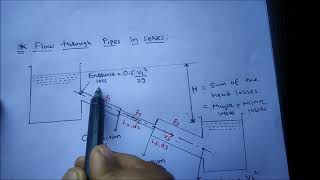
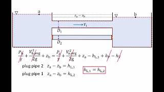
Pipe in series is a very simple problems like electric circuits, okay. You can have a series of wires you have from point A to B, okay. ... But if you are having a energy losses between delta h 1 is energy losses for this regions.
Detailed Explanation
In a series configuration of pipes, the flow rate is constant through all pipes, meaning that the discharge (Q) remains the same. However, energy losses due to friction and changes in elevation must be summed over each pipe. Therefore, the total head loss is the sum of head losses from individual pipes. This creates a straightforward calculation model based on the fixed flow.
Examples & Analogies
Imagine water flowing through multiple connected hoses. If one hose is kinked, it reduces the pressure throughout the entire system. To understand the energy loss, think about how much pressure is needed to push water through each kinked hose separately.
Considering Energy Losses
Chapter 3 of 6
🔒 Unlock Audio Chapter
Sign up and enroll to access the full audio experience
Chapter Content
But when you have a pipe in a series please remember it that you always should consider whether there is a minor losses. ... the head energy losses along the pipe from pipe 1, pipe 2, pipe 3.
Detailed Explanation
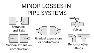
When analyzing a series pipe system, both major losses (friction from the pipe surface) and minor losses (losses due to fittings, expansions, and contractions) must be accounted for. This ensures accurate predictions of total energy losses and helps in designing efficient pipe systems.
Examples & Analogies
Consider a long garden hose connected to various attachments. Not only does the friction inside the hose slow down the water (major loss), but also every attachment, such as a sprinkler or nozzle, creates additional obstacles, causing more water pressure to be lost (minor losses).
Forwarding Through Pipes in Parallel
Chapter 4 of 6
🔒 Unlock Audio Chapter
Sign up and enroll to access the full audio experience
Chapter Content
Now if you look it another very simple problems that pipes in parallel. ... So sum of the discharge will give us the discharge what is passing through the A or B and the energy losses whether following the 1 path 2 path or 3 path should be equal.
Detailed Explanation
In a parallel pipe configuration, multiple paths allow water to flow simultaneously, similar to how traffic can divide into multiple lanes on a road. Here, the energy loss in each path must be equal, meaning that if one path has higher resistance, the fluid will adjust its flow accordingly. The total flow entering the parallel system equals the sum of discharges in each of the outlets.
Examples & Analogies
Think about highways in a city where traffic can take multiple routes. Even if one route is jammed, cars will divert to other routes, making sure the total number of cars trying to reach the city center remains constant, just like how fluid divides and takes different paths based on resistance in parallel pipes.
Three Reservoir Junction Problems
Chapter 5 of 6
🔒 Unlock Audio Chapter
Sign up and enroll to access the full audio experience
Chapter Content
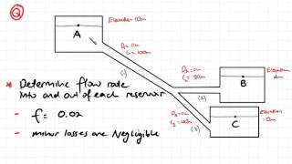
Now if you look it the three reservoir junction problems which many of the time it is given that you have a multiple reservoirs ... That is what we apply with a loss and compute what is the head losses should be there in this direction.
Detailed Explanation
At a junction with three reservoirs, the principle of mass conservation applies, meaning the total incoming flow minus the outgoing flow must equal zero. The head (energy) loss must also be calculated across the junction to understand how much fluid can exit through various pipes. By understanding this, engineers can ensure that the system is designed to maintain sufficient pressure and flow.
Examples & Analogies
Think of a water park where three different slides (reservoirs) are connected at a point. If too many kids (fluid) go down one slide while the others remain unused, it might drain some slides faster than others, leading to flow imbalances. We must ensure that water can continuously flow by analyzing how much is lost at each junction.
Example from GATE Exam
Chapter 6 of 6
🔒 Unlock Audio Chapter
Sign up and enroll to access the full audio experience
Chapter Content
Let us start this third examples which is gives that 2 kilometer long pipe with a diameter of 0.2 meter ... additional things what will consider it, but other losses we will not consider this case as given in the problems.
Detailed Explanation
This example illustrates a typical examination scenario where students must calculate the average velocity of the fluid flowing through a long pipe with defined friction losses. By understanding both major and minor losses, students can apply the concepts learned to find the effective flowing speed, indicating how friction and energy loss impacts the flow.
Examples & Analogies
Imagine a long water slide where the speed of water changes due to friction against the slide's surface. The height difference between two ends of the slide represents potential energy that can be lost through friction, similar to how we lose energy in pipes; calculating these losses helps to find out the water's speed at the bottom of the slide.
Key Concepts
-
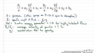
Velocity Defect: It measures the deviation of instant velocity from average velocity, crucial in turbulent flow analysis.
-
Energy Losses: Understanding that both major (friction) and minor (fittings) losses contribute significantly to total flow energy loss.
-
Pipe Configurations: Recognizing the different implications of flow arrangements—series vs. parallel—on overall system efficiency and analysis.
Examples & Applications
Example of calculating total head loss for a series of pipes in a given system, considering both major and minor losses.
Problem where flow is distributed across parallel pipes, requiring an understanding of how to balance energy losses across different pathways.
Memory Aids
Interactive tools to help you remember key concepts
Rhymes
Flow in a pipe, keep it right, friction causes loss, give it all your might!
Stories
Imagine a pipeline race, where each runner represents fluid flow; they face friction as hurdles and navigate smooth passages to get from start to endpoint efficiently.
Memory Tools
MVP for remembering 'Major losses, Velocity defects, Pipe configurations.'
Acronyms
FLOW - 'Friction Losses Over Weirs.' This reminds us that friction affects flow in various settings.
Flash Cards
Glossary
- Velocity Defect
The difference between the instantaneous velocity of a fluid and its average velocity.
- Major Losses
Losses in energy in a fluid flow system primarily due to friction along the pipe wall.
- Minor Losses
Energy losses that occur at fittings, bends, or changes in diameter in a fluid system.
- Head Loss
The loss of energy in a fluid due to friction, turbulence, and other factors.
- Continuity Equation
An equation that represents the conservation of mass in fluid flow, ensuring that mass entering a system equals mass exiting.
Reference links
Supplementary resources to enhance your learning experience.