
Three Reservoir Junction Problems
Enroll to start learning
You’ve not yet enrolled in this course. Please enroll for free to listen to audio lessons, classroom podcasts and take practice test.
Interactive Audio Lesson
Listen to a student-teacher conversation explaining the topic in a relatable way.
Pipes in Series
🔒 Unlock Audio Lesson
Sign up and enroll to listen to this audio lesson

Today, we're going to begin with pipes in series. Can anyone explain what that means?

It means there's a sequence of pipes connected end to end.
Exactly! And what can we say about the discharge through each pipe?

The discharge should be the same in each pipe, right?
Correct! When analyzing these systems, we summarize the head loss as the sum of individual losses. Can anyone tell me what kinds of losses we're considering?

Major losses from friction and minor losses when the pipe geometry changes?
Great answer! Let’s remember this relationship as **H_total = H_major + H_minor** for future reference!
To summarize, in pipes in series, the same discharge flows through each pipe, and total head loss is the summation of individual losses.
Pipes in Parallel
🔒 Unlock Audio Lesson
Sign up and enroll to listen to this audio lesson

Next, let’s discuss pipes in parallel. How does flow behave in such systems?

The flow divides between two or more pipes, right?
Exactly! What must we remember regarding energy loss through these pathways?
The energy losses should be equal for each path.
Good observation! This condition allows us to formulate equations that relate the various discharges. Why is this significant?
It helps in designing systems, so they work efficiently!
Correct! To wrap up, remember that in parallel pipes, the total energy losses must equalize across paths for proper flow assessment.
Three Reservoir Junction Problems
🔒 Unlock Audio Lesson
Sign up and enroll to listen to this audio lesson
Now, let's explore a more complex scenario—three reservoir junction problems. What happens at these junctions?
There are multiple water levels, and the flow has to be analyzed at the junction point.
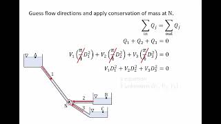
Exactly! The key principle here is continuity: the sum of inflow and outflow must be zero. Can anyone explain how we might express this mathematically?
We say Q1 + Q2 - Q3 = 0, where Q3 could be an outflow?
Correct! Additionally, we analyze energy gradients. How do head losses relate to the flow through the junction?
The energy losses impact the hydraulic gradient, and we need balances to calculate actual flow rates!
Precisely! In summary, at three reservoir junctions, we apply mass conservation and energy analysis for effective flow management.
Introduction & Overview
Read summaries of the section's main ideas at different levels of detail.
Quick Overview
Standard
The content explores fluid dynamics, specifically addressing three key configurations of pipe systems: series, parallel, and three reservoir junctions. It highlights energy losses (major and minor) and the importance of understanding steady-state flow conditions to predict discharge and hydraulic gradients effectively.
Detailed
Detailed Summary
This section delves into the analysis of fluid dynamics in three primary configurations of pipe systems: pipes in series, pipes in parallel, and the three reservoir junction problems. The flow in these systems is governed by the principles of mass conservation and energy losses due to friction.
Key Concepts:
- Pipes in Series: The discharge remains constant across the series, while total head loss is the sum of head losses in each pipe.
- Pipes in Parallel: In parallel arrangements, total energy losses through the paths must be equal, allowing us to equate the flows between different branches.
- Three Reservoir Junction Problems: At junctions of multiple reservoirs, continuity equations dictate that the sum of discharges equals zero. Determining hydraulic gradients and energy losses is essential for analyzing flow directions at these points. Multiple examples—including applications for practical problems—illustrate the analytical approaches needed to calculate energy losses and flow rates effectively. This understanding forms a critical foundation for predictive modeling in fluid systems.
Youtube Videos
Audio Book
Dive deep into the subject with an immersive audiobook experience.
Introduction to Three Reservoir Junction Problems
Chapter 1 of 5
🔒 Unlock Audio Chapter
Sign up and enroll to access the full audio experience
Chapter Content
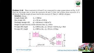
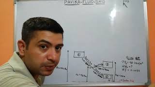
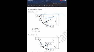
Now if you look it the three reservoir junction problems which many of the time it is given that you have a multiple reservoirs okay. You may have the multiple water tanks are there and connected to the pipe flow systems and you have a junctions where you have three are connected here. Out of these three flow one could be also outflow. We do not know that which direction it will be, outflow it.
Detailed Explanation
In this section, we introduce the concept of three reservoir junction problems. These problems often involve multiple water tanks (or reservoirs) connected through pipes at junctions. At these junctions, flows can come from or go to these reservoirs, and it's important to analyze how the water flows between them. One of the crucial aspects of these junctions is that we may have an outflow, meaning that if a particular reservoir has a higher water level, it may let water flow to the other reservoirs.
Examples & Analogies
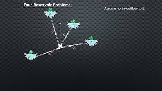
Imagine a set of three water tanks at different elevations connected with pipes. If the water level in one tank is high, water will flow down through the pipes to the other tanks until equilibrium is reached. Understanding how much water will flow and where it goes is essential for proper design and management of water resources.
Continuity Equation and Mass Conservation
Chapter 2 of 5
🔒 Unlock Audio Chapter
Sign up and enroll to access the full audio experience
Chapter Content
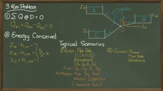
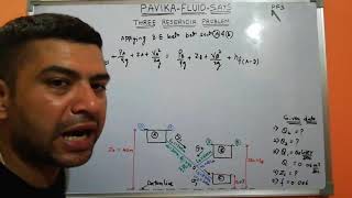
But we can say that some of the Q discharge should be equal to zero at this point. There is no outlet, okay. So at the junction point, the continuity equations are mass conservations at these equations should be equal to zero.
Detailed Explanation
At the junction of the three reservoirs, the principle of conservation of mass applies, referred to as the continuity equation. It states that the sum of inflows must equal the sum of outflows for a steady flow condition. In this case, if there is no outflow at the junction, it means the total discharge, represented as 'Q', must sum to zero. This concept is crucial for analyzing the flow rates and ensuring that the system operates sustainably without excess loss of water.
Examples & Analogies
Think of the water flowing in as being like traffic at an intersection where all roads (pipes) lead to that point. If cars (water) are coming in but not going out, the intersection becomes congested (increasing water level), similar to how water level rises if there’s no outflow at our junction.
Hydraulic Gradient at the Junction
Chapter 3 of 5
🔒 Unlock Audio Chapter
Sign up and enroll to access the full audio experience
Chapter Content
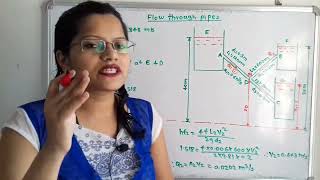
But another one what you need to compute it how much of energy or the head is what is the elevations of high gradient line. These hydraulic gradient is supposed to be equal to yours the change of we have this gradient line at this point like this.
Detailed Explanation
At the junction of the reservoirs, another important consideration is the hydraulic gradient, which indicates the change in pressure head due to differences in elevation among the water levels in the reservoirs. Since pressure heads can vary significantly depending on each reservoir's elevation and water level, calculating this gradient is essential for ensuring efficient flow through the pipes connecting the reservoirs. It estimates how energy is lost due to changing hydraulic levels.
Examples & Analogies
Imagine you're water skiing behind a boat. The higher the boat is compared to the water level, the more potential energy you have, which translates into how fast you can go. Similarly, in our reservoirs, the higher the water elevation, the stronger the 'push' it provides to move water through the connecting pipes.
Calculating Energy Losses
Chapter 4 of 5
🔒 Unlock Audio Chapter
Sign up and enroll to access the full audio experience
Chapter Content
So how much of energy losses will happen in such a way that we will have a hydraulic gradient at the junctions will be this ones. That is what we apply with a loss and compute what is the head losses should be there in this direction in this direction and in this direction, okay.
Detailed Explanation
When analyzing the flow in three reservoir junctions, calculating energy losses is critical. As water flows through pipes, it experiences friction and other losses that can affect the efficiency of the flow. These losses need to be quantified to assess how well the system is functioning. Energy losses can be computed based on the hydraulic gradients and flow paths, helping to determine the relevant discharge values in each direction at the junction.
Examples & Analogies
Consider a car driving uphill; it needs more energy (fuel) to overcome gravity compared to driving on a flat road. Similarly, water must have enough 'energy' to overcome friction in the pipes. If we can measure how much energy is lost, we can better understand what conditions need to be met to keep the water flowing effectively, similar to ensuring your car has enough fuel to reach its destination.
Practical Application in Problem Solving
Chapter 5 of 5
🔒 Unlock Audio Chapter
Sign up and enroll to access the full audio experience
Chapter Content
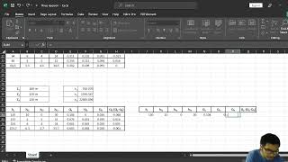
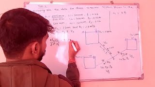
Now come back to a example one which is a GATE 2014 question paper which looks like very lengthy but is a very simple problems okay.
Detailed Explanation
This section introduces an example problem from the GATE 2014 examination, which deals with the principles discussed earlier in a practical scenario. Students will see how the theoretical principles of the three reservoir junction problems apply to real-life situations by calculating flow rates or pressures under specific conditions given the variables like discharge and reservoir heights.
Examples & Analogies
Picture preparing a dish with different ingredients and adjusting them to achieve the perfect taste. Just as each ingredient must be measured and balanced, in flow problems of reservoirs, we have specific values to work with (like flow rates and pressure heads) that affect the overall system's functioning, just as they affect the dish's final flavor.
Key Concepts
-
Pipes in Series: The discharge remains constant across the series, while total head loss is the sum of head losses in each pipe.
-
Pipes in Parallel: In parallel arrangements, total energy losses through the paths must be equal, allowing us to equate the flows between different branches.
-
Three Reservoir Junction Problems: At junctions of multiple reservoirs, continuity equations dictate that the sum of discharges equals zero. Determining hydraulic gradients and energy losses is essential for analyzing flow directions at these points. Multiple examples—including applications for practical problems—illustrate the analytical approaches needed to calculate energy losses and flow rates effectively. This understanding forms a critical foundation for predictive modeling in fluid systems.
Examples & Applications
If three reservoirs are connected and one reservoir is at a higher elevation, the hydraulic gradients help calculate the flow direction and rate into the lower reservoirs.
In a system of pipes in parallel, if each pipe has different diameters, their respective head losses must be calculated and set equal to solve for flow rates.
Memory Aids
Interactive tools to help you remember key concepts
Rhymes
In series, the flow must agree, losses sum to see!
Stories
Imagine water flowing from a high mountain through a series of pipes. Each pipe loses some energy until it flows through series, where they all lose energy together.
Memory Tools
S.E.R. - Series Equalizes Resistances: remember for pipes in series discharges are equal while accounting for losses.
Acronyms
H.E.L.P. - Hydraulic Energy Loss Principles
always remember the loss due to friction and geometry changes.
Flash Cards
Glossary
- Head Loss
The reduction in total head of the fluid as it moves through a system due to friction and other resistances.
- Steady State Flow
A condition where fluid properties do not change with time at any given point in the system.
- Energy Gradient Line
A line that represents the energy levels at different points in a fluid system, considering pressure head, elevation head, and velocity head.
- Hydraulic Gradient
The slope of the energy line as defined by changes in height due to energy losses throughout the system.
- Minor Losses
Small energy losses in a fluid system due to fittings, bends, expansions, and contractions that alter the flow.
Reference links
Supplementary resources to enhance your learning experience.