
Major and Minor Losses
Enroll to start learning
You’ve not yet enrolled in this course. Please enroll for free to listen to audio lessons, classroom podcasts and take practice test.
Interactive Audio Lesson
Listen to a student-teacher conversation explaining the topic in a relatable way.
Understanding Major and Minor Losses
🔒 Unlock Audio Lesson
Sign up and enroll to listen to this audio lesson

Today, we will discuss the differences between major and minor losses in piping systems. Can anyone tell me what they think major losses refer to?

Does it involve energy lost due to friction in the pipes?
Exactly! Major losses primarily come from friction as the fluid flows through long pipes. Now, what about minor losses?

Are those the losses from valves or changes in direction?
Yes, correct! Minor losses arise from fittings, bends, or any abrupt changes in flow. These factors can significantly impact the efficiency of fluid systems.
Calculating Major Losses
🔒 Unlock Audio Lesson
Sign up and enroll to listen to this audio lesson

Let’s dive into calculating major losses using the Darcy-Weisbach equation. Who can recall the formula?

It's = f * (L/D) * (V^2 / 2g), right?
That’s correct! Where represents the head loss due to friction, f is the friction factor, L is the pipe length, D is the diameter, and V is the flow velocity. Anyone have questions about this?

What if the diameter of the pipe changes along its length?
In such cases, you need to evaluate the losses separately for each section of the pipe based on its diameter.
Combining Major and Minor Losses
🔒 Unlock Audio Lesson
Sign up and enroll to listen to this audio lesson
When analyzing a piping system, how do we account for both major and minor losses?
Do we just add them together?
Yes! The total head loss is the sum of major losses and minor losses. For pipes in series, we simply add up the losses from all sections.
And in parallel systems, we need to ensure that energy losses are equal for all paths.
Exactly! That’s a crucial point in designing efficient systems. Let's make sure to always compute both types of losses.
Introduction & Overview
Read summaries of the section's main ideas at different levels of detail.
Quick Overview
Standard
In this section, we delve into the concepts of major and minor losses in fluid systems. Major losses mainly refer to energy losses resulting from friction while flowing through pipes, and minor losses are caused by changes in flow direction or cross-section. The section elaborates on calculations for head loss in series and parallel pipe systems, highlighting practical applications such as reservoir junction flows.
Detailed
Major and Minor Losses
In fluid dynamics, the concept of energy losses is vital for understanding how fluids behave in piping systems. These losses can be categorized primarily into major and minor losses:
Major Losses
Major losses refer to energy losses due to friction as fluid flows through a long pipe. The Darcy-Weisbach equation allows us to calculate head loss ( ) due to friction, which is directly proportional to pipe length, flow velocity, and inversely proportional to diameter. Understanding the implications of the frictional losses is crucial for effective system design.
Minor Losses
Minor losses, on the other hand, occur due to changes in flow direction or cross-section, such as in fittings, bends, or valves. These losses are often expressed in terms of loss coefficients specific to the components involved. It is important to consider both major and minor losses when designing fluid systems, especially in applications involving multiple pipe configurations such as series and parallel systems.
In scenarios involving pipes in series, the total head loss is the sum of head losses from individual pipes, including both major and minor losses. For pipes in parallel, the energy loss must be equal across all paths, aiding in determining flow distribution. Practical examples illustrate calculation techniques and real-world applications, emphasizing the importance of energy conservation in fluid systems.
Youtube Videos


![[MAE 242] Pipe flow with major and minor head losses](https://img.youtube.com/vi/WH1fn6dMYiw/mqdefault.jpg)


Audio Book
Dive deep into the subject with an immersive audiobook experience.
Understanding Major and Minor Losses
Chapter 1 of 5
🔒 Unlock Audio Chapter
Sign up and enroll to access the full audio experience
Chapter Content
When you have pipes in series or parallel, it's essential to consider both major and minor losses. Major losses refer to frictional losses in the pipes, while minor losses occur due to changes in the flow path such as fittings, bends, and exits.
Detailed Explanation
In fluid dynamics, when fluid flows through a pipe, it encounters resistance due to friction between the fluid and the pipe wall. This resistance causes what we call 'major losses.' Conversely, when a pipe experiences changes in diameter, direction, or other fittings, these cause additional 'minor losses.' Both types of losses affect the overall energy required for fluid flow.
Examples & Analogies
Think of water flowing through a garden hose. If you’ve ever tried to water your garden with a hose that has kinks or has different attachments, you’ll notice that the water comes out less forcefully than from a straight, unblocked hose. The friction along the hose walls represents major losses, while the kinks and attachments represent minor losses.
Pipes in Series: Calculation of Head Losses
Chapter 2 of 5
🔒 Unlock Audio Chapter
Sign up and enroll to access the full audio experience
Chapter Content
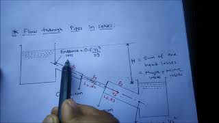
For pipes in series, the total head loss is the sum of individual head losses across each pipe. For steady state conditions, the flow rate should remain constant across each pipe.
Detailed Explanation
When dealing with multiple pipes connected in a series, we can visualize it like a chain. Each segment (or pipe) has some resistance to flow, causing energy (or head) loss. The head loss in each pipe is additive; meaning, to find the total head loss, you add the head loss values for each pipe in the series.
Examples & Analogies
Imagine riding a bike up a hill made of several small slopes. Each slope requires you to exert energy, and the steeper the slope, the more energy you need to climb. The total energy (or head loss) you need to reach the top of the hill is simply the sum of the energy needed for each slope.
Minor Losses in Series
Chapter 3 of 5
🔒 Unlock Audio Chapter
Sign up and enroll to access the full audio experience
Chapter Content
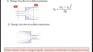
In addition to major losses, it's important to account for minor losses due to changes in the pipe configuration, such as expansions, contractions, and bends. Minor losses impact the total energy losses significantly.
Detailed Explanation
Minor losses, while usually smaller than major losses, can accumulate and have a significant effect in complex piping systems. These losses occur at points where the flow changes direction or speed. For example, when fluid enters a larger section after exiting a narrow pipe, there is turbulence created that can cause energy loss.
Examples & Analogies
Imagine turning a corner while riding a bicycle at high speed; the sudden change in direction can make you lose momentum and require additional effort to pedal back to a stable speed. In piping systems, these bends and turns cause similar effects, increasing the effort (energy) needed to maintain desired flow.
Pipes in Parallel: Distribution of Flow and Energy Losses
Chapter 4 of 5
🔒 Unlock Audio Chapter
Sign up and enroll to access the full audio experience
Chapter Content
In parallel pipes, energy losses must also be equal across different paths. The total flow rate is divided among the parallel pipes, and energy loss calculations must account for all paths taken.
Detailed Explanation
When multiple pipes run parallel to each other, fluid can flow through any of these pipes. Despite each pipe potentially having different dimensions or friction characteristics, the energy lost while flowing through each path will be equal at the junctions where they meet. This means you have to analyze each pipe's losses and ensure they equal out for steady flow conditions.
Examples & Analogies
Consider a busy intersection with multiple streets leading to the same destination. Even if each street has different traffic patterns, ultimately, the vehicles arriving at the destination from each street will provide a combined flow that needs to be managed equally to prevent jams — portraying how energy losses need to be balanced in parallel piping systems.
Three Reservoir Junction Problems
Chapter 5 of 5
🔒 Unlock Audio Chapter
Sign up and enroll to access the full audio experience
Chapter Content
When analyzing junctions with multiple reservoirs, ensure that the continuity equations are satisfied at junction points, accounting for the sum of flow rates equating to zero.
Detailed Explanation
In a system with multiple reservoirs linked by pipes, flows can either enter or leave through different junction points. To maintain continuity, the sum of inflows should equal the sum of outflows. This conservation of mass principle ensures that energy losses due to friction, bends, or fittings are accurately represented throughout the entire system.
Examples & Analogies
Think of a water fountain where several pipes deliver water from a reservoir. If one pipe is blocked and not delivering water, the others have to compensate to keep the fountain functioning well without overflowing or draining dry. Thus, effective management of energy and flow maintains the system's balance.
Key Concepts
-
Major Losses: Involves energy loss due to friction within the pipe.
-
Minor Losses: Pertains to losses due to changes in flow direction or cross-section.
-
Darcy-Weisbach Equation: A formula to quantify head loss in relation to flow characteristics.
-
Friction Factor: A vital component in determining flow resistance.
-
Total Head Loss: The summation of both major and minor losses in a system.
Examples & Applications
Example 1: Calculate head loss in a 100m pipe with a diameter of 0.3m and a friction factor of 0.02 at a velocity of 2 m/s.
Example 2: A system with three parallel pipes has different diameters. Calculate the total energy loss considering both major and minor losses.
Memory Aids
Interactive tools to help you remember key concepts
Rhymes
Major flows tap, friction's a trap, minor bends and losses in the map.
Stories
Imagine a river flowing smoothly in a straight line (major loss), then suddenly hitting a bend and splashing—losing energy (minor loss).
Memory Tools
Fried Chicken Can Be Provided to Remember: Friction, Coefficients, Calculate, Both (Major and Minor losses).
Acronyms
MEMO
Major Energy Losses from Friction
Minor from Manifold Changes.
Flash Cards
Glossary
- Major Losses
Energy losses due to friction as fluid flows through long pipes.
- Minor Losses
Energy losses occurring due to changes in direction or cross-section in piping systems.
- DarcyWeisbach Equation
An equation used to calculate the head loss due to friction in a pipe.
- Friction Factor (f)
A dimensionless number used in the Darcy-Weisbach equation that represents the resistance to flow.
- Head Loss (h)
The loss of pressure or energy in a fluid caused by friction or other factors.
Reference links
Supplementary resources to enhance your learning experience.