
Coefficients of Discharge
Enroll to start learning
You’ve not yet enrolled in this course. Please enroll for free to listen to audio lessons, classroom podcasts and take practice test.
Interactive Audio Lesson
Listen to a student-teacher conversation explaining the topic in a relatable way.
Understanding Hydraulic Gradient Lines
🔒 Unlock Audio Lesson
Sign up and enroll to listen to this audio lesson

Today, let's explore hydraulic gradient lines. In open channel flows, the hydraulic gradient coincides with the liquid's free surface. Can anyone explain why?

Is it because there's no pressure head in open channels?
That's correct! The absence of pressure head means the water surface represents the hydraulic gradient. Now, how does this change in closed systems like pipes?

In pipes, we can measure hydraulic gradients using devices like piezometers, right?
Exactly! Piezometers give us insight into pressure head. Remember, the hydraulic gradient line will align with the pipe's outlet when the pressure head transitions to atmospheric pressure.
To remember this, think of the acronym 'PAH', which stands for Pressure, Atmosphere, Hydraulic – ensuring we always link these concepts together.

Got it! So, in both systems, pressure alignment is crucial.
Yes, pressures directly relate to flow dynamics in fluid systems. Let's recap: hydraulic gradient lines align with free surfaces in open channels, and with atmospheric pressure at pipe outlets.
Energy Gradients and Mechanical Energy Loss
🔒 Unlock Audio Lesson
Sign up and enroll to listen to this audio lesson

Moving on, let’s discuss energy gradient lines. Who can tell me how they differ from hydraulic gradient lines, especially in open channels?

Energy gradients include the velocity head above the free surface, right?
Spot on! The energy gradient accounts not just for pressure, but also kinetic energy. As for energy losses due to friction, how do these affect our gradient lines?
They slope downwards in the direction of flow, reflecting energy lost to friction, I think.
Exactly! Remember: energy losses create a downward slope in energy gradients. A mnemonic to reinforce this is 'FLEES' — Friction Leads to Energy Slope.
That makes it easier to remember! Energy losses are critical in understanding flow!
Absolutely! Always consider the energy lost through friction as it directly impacts flow efficiency.
Pump and Turbine Functions
🔒 Unlock Audio Lesson
Sign up and enroll to listen to this audio lesson
Now, let’s explore pumps and turbines. Who can explain the role of a pump in a fluid system?
A pump increases the mechanical energy in the fluid by raising the pressure, right?
Correct! And what about turbines?
Turbines extract mechanical energy by reducing the pressure in the fluid.
Exactly! So remember: 'Pumps Push, Turbines Take.' Keep this in mind when discussing mechanical energy in fluid systems.
It's clear now! Pumps and turbines play opposite roles.
Exactly! Let's recap: pumps add energy while turbines extract energy. Understanding their roles is vital for system efficiency.
Coefficient of Discharge
🔒 Unlock Audio Lesson
Sign up and enroll to listen to this audio lesson
Finally, we need to talk about the coefficient of discharge. What do you all understand by this term?
Is it a ratio of actual discharge to theoretical discharge?
That’s correct! The coefficient of discharge is crucial for calculating the performance of devices like venturi meters.
So, it's affected by factors like velocity and pressure changes.
Yes! The term 'CD' can help you remember it stands for Coefficient of Discharge. Why is it important in field measurements?
It helps us understand how efficient a flow system is in real conditions compared to ideal ones.
Excellent! Efficiency ratios are vital in fluid dynamics. To wrap up, the coefficient is about real vs. theoretical flow. Ensure you remember how it relates to energy loss as well!
Introduction & Overview
Read summaries of the section's main ideas at different levels of detail.
Quick Overview
Standard
In this section, the concepts of hydraulic and energy gradient lines are explored, focusing on the impact of pressure changes at fluid outlets and how mechanical energy is converted in engineering applications involving pumps and turbines. It also introduces the coefficient of discharge and its significance in lab measurements and real-world applications.
Detailed
Coefficients of Discharge (4.3)
This section delves into the principles underlying coefficients of discharge, focusing on the behavior of fluid flow in both open channels and pipes. In open channel scenarios, the hydraulic gradient lines coincide with the free surface of liquid, as there is no pressure head, while energy gradient lines integrate velocity head components. As flow exits pipes to the atmosphere, pressure head becomes atmospheric, aligning the hydraulic gradient with the pipe outlet. The text highlights that mechanical energy losses, caused by friction, lead to downward slopes in both the energy and hydraulic gradient lines.
The significance of pumps and turbines is examined, with pumps transferring mechanical energy to fluid by increasing pressures, while turbines extract energy by decreasing pressure. Importantly, the section clarifies that pressure is a form of potential energy rather than direct energy. Furthermore, it discusses how theoretical principles, such as Bernoulli's equations, can be applied to determine the mechanical energy difference across two flow points, incorporating efficiency ratios to relate input and output mechanical power.
The section wraps up with practical challenges in fluid dynamics measurements, using real-world applications such as venturi tubes and evaluating hydraulic gradient changes to determine discharge coefficients, emphasizing efficiency factors and energy loss considerations.
Youtube Videos


Audio Book
Dive deep into the subject with an immersive audiobook experience.
Understanding Hydraulic Gradients in Open Channels
Chapter 1 of 4
🔒 Unlock Audio Chapter
Sign up and enroll to access the full audio experience
Chapter Content
Whenever a pipe exits, the pressure head becomes atmospheric pressure, making the hydraulic gradient line coincide with the pipe outlet. Mechanical energy losses due to friction convert thermal energy, causing the energy gradient line and the hydraulic gradient line to slope downwards in the direction of flow.
Detailed Explanation
In open channel flow, the hydraulic gradient line represents the energy available to the fluid. When fluid flows out of a pipe, the pressure at that exit point is equal to the atmospheric pressure, which causes the hydraulic gradient line to align with this level. The energy gradient line, which considers additional factors like kinetic (velocity) energy, will slope downwards due to energy loss from frictional effects. This slope indicates that with increased distance down the flow direction, available energy decreases due to mechanical losses.
Examples & Analogies
Imagine a playground slide. At the top, you have maximum potential energy. As you slide down, that potential energy is converted to kinetic energy and eventually to friction (which you can feel slowing you down). Similarly, as water flows through a pipe and exits, energy is lost due to friction with the sides of the pipe, just like you would lose some speed against the slide surface.
Pressure Changes Relative to Hydraulic Gradient Line
Chapter 2 of 4
🔒 Unlock Audio Chapter
Sign up and enroll to access the full audio experience
Chapter Content
Pressure in a flow section above the hydraulic gradient line is negative, while pressure below is positive. When solving pipe flow problems, the transition of pressures from negative to positive in relation to the hydraulic gradient line will be demonstrated.
Detailed Explanation
The hydraulic gradient line helps visualize how pressure changes within a fluid system. If a pressure reading is above this line, it indicates a potential negative pressure or vacuum. Conversely, any pressure reading below denotes a positive pressure situation. This relationship is vital for engineers and scientists as it informs them how fluid behaves under various conditions, especially when designing systems that involve flow through pipes.
Examples & Analogies
Think of a sealed straw in a drink. If you place your finger over the straw’s top while it's submerged in a drink, you create a negative pressure (vacuum) within the straw. The drink doesn’t flow out until you remove your finger—representing a pressure above the hydraulic gradient line. Once you lift your finger, the drink rushes up the straw due to the pressure below the hydraulic gradient line coming into play.
The Role of Pumps and Turbines
Chapter 3 of 4
🔒 Unlock Audio Chapter
Sign up and enroll to access the full audio experience
Chapter Content
Pumps transfer mechanical energy to fluid by raising pressures, while turbines extract mechanical energy from fluids by reducing pressures. This relationship is crucial in systems such as water supply and hydropower projects.
Detailed Explanation
Pumps and turbines operate as two sides of the same coin in fluid mechanics. Pumps push fluids by increasing their pressure, effectively transferring energy to the fluid. Conversely, turbines extract energy from flowing fluids, usually resulting in a drop in fluid pressure. Understanding the operation of each device helps optimize energy usage and system design in applications like municipal water systems and hydropower generation.
Examples & Analogies
Consider a water fountain. When you turn on the pump, water shoots upward against gravity, showcasing how the pump increases pressure. Now, when that water flows over, it drives a turbine which powers lights or other devices. It is a perfect cycle of energy transfer: the pump pushes the water up, and as it flows back down, it generates power.
Efficiency of Fluid Systems
Chapter 4 of 4
🔒 Unlock Audio Chapter
Sign up and enroll to access the full audio experience
Chapter Content
Efficiency in pumps and turbines is crucial to understanding energy losses. The relationship between input and output power, as well as the formulas for calculating efficiency, demonstrate how real systems deviate from ideal performance.
Detailed Explanation
Efficiency in fluid systems measures how well energy input translates into useful work output. Pumps and turbines, irrespective of design, will always have some level of energy loss, be it through heat or sound. The formula for efficiency, defined as the ratio of useful power output to total power input, allows engineers to evaluate performance and improve designs. A system's efficiency will dictate its economic viability and environmental impact by minimizing energy losses.
Examples & Analogies
Think of a car engine. If you pour fuel into the tank, only a fraction of that energy translates into movement due to various losses like heat and friction. Similarly, in fluid systems, pumps and turbines have efficiency ratings that signify how much of the energy is actually used for effective work versus how much is wasted.
Key Concepts
-
Hydraulic Gradient Line: Represents the potential energy head in a fluid system.
-
Energy Gradient Line: Integrates velocity head with hydraulic gradient, indicates total energy.
-
Coefficient of Discharge: Measures the efficiency of fluid flow devices.
-
Pressure Head: The height of fluid in a vessel, reflecting potential energy.
-
Mechanical Energy Loss: Energy lost due to friction in fluid flow.
Examples & Applications
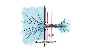
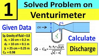
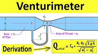
In a venturi meter, the pressure difference across the throat allows for calculation of flow rate based on the coefficient of discharge.
When analyzing energy gradients, changes in pressure and velocity through pumps and turbines illustrate practical application in engineering efficiency.
Memory Aids
Interactive tools to help you remember key concepts
Rhymes
Flow with ease, see the freeze, pressure up, then go down, fluid flow is all around.
Stories
Imagine a river where boats sail. Each boat floats smoothly as the current guides them, illustrating the balance of hydraulic forces in nature.
Memory Tools
PAH for remembering Pressure, Atmosphere, Hydraulic: pressure aligns with atmosphere at fluid outlets.
Acronyms
FLEES - Friction Leads to Energy Slope to recall how friction changes energy gradient lines.
Flash Cards
Glossary
- Hydraulic Gradient Line
A line that represents the height to which water would rise in a piezometer tube; in open channels, it coincides with the free surface.
- Energy Gradient Line
A line that includes the velocity head above the hydraulic gradient line, indicating the total energy per unit weight of fluid.
- Coefficient of Discharge (CD)
The ratio of actual discharge to theoretical discharge, indicating the efficiency of a flow device.
- Piezometer
A device used to measure the pressure head in a fluid at a specific point.
- Turbine
A machine for converting kinetic energy from fluid into mechanical energy, typically by reducing fluid pressure.
- Pump
A device used to increase the pressure and mechanical energy of a fluid.
- Bernoulli’s Equation
An equation relating pressure, velocity, and elevation in incompressible flow; used for energy conservation analysis.
Reference links
Supplementary resources to enhance your learning experience.