
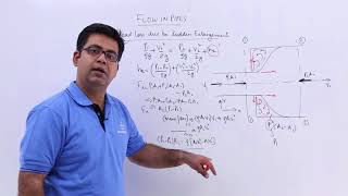
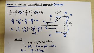
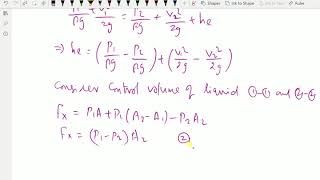
Sudden Enlargement of Pipeline
Enroll to start learning
You’ve not yet enrolled in this course. Please enroll for free to listen to audio lessons, classroom podcasts and take practice test.
Interactive Audio Lesson
Listen to a student-teacher conversation explaining the topic in a relatable way.
Understanding Hydraulic Gradient Lines
🔒 Unlock Audio Lesson
Sign up and enroll to listen to this audio lesson

Today, we're going to discuss hydraulic gradient lines. Can anyone tell me what a hydraulic gradient line represents in fluid dynamics?

Is it the height of the water column or the pressure in the system?
Good thought, Student_1! The hydraulic gradient line correlates to the energy available to the fluid. In open channels, it aligns with the free surface due to atmospheric pressure. In pipes, it coincides with the outlet when the pressure is atmospheric.

So does that mean the water's kinetic energy affects how high it can go?
Exactly! The velocity head also factors into the energy gradient line. Remember this: 'Velocity impacts energy!'

Can we see how the energy decreases along the flow?
Yes! Mechanical energy losses from friction cause a slope downwards in the energy gradient line.

What about when we calculate pressures in the flow sections?
That's crucial! Pressures above the hydraulic gradient line are negative, while those below it are positive. Let’s summarize: Hydraulic gradient lines reveal energy in the flow, affected by kinetic energy and pressure differences.
Mechanisms of Pumps and Turbines
🔒 Unlock Audio Lesson
Sign up and enroll to listen to this audio lesson

Let’s explore how pumps and turbines operate. Can anyone explain what a pump does?
A pump increases the fluid's pressure, right?
Correct! It converts mechanical energy into fluid energy, raising pressure. Now, how about turbines?
Turbines extract energy from fluid flow, lowering the pressure?
Exactly! This interplay of energy is fundamental for fluid systems. Remember this: 'Pumps push, turbines pull!'
And what about efficiency? Does energy loss affect it?
Great question! Mechanical efficiency is influenced by losses like heat and sound, which we quantify. It’s key to design effective systems.
How do we calculate this efficiency?
Efficiency = Output Power / Input Power. Keep that formula handy as we will use it often in engineering!
Applying Bernoulli's Equation
🔒 Unlock Audio Lesson
Sign up and enroll to listen to this audio lesson
Now, let’s apply Bernoulli’s equation to fluid flow problems. Who remembers the equation?
Isn’t it relating pressures, height, and velocity?
Yes! It's crucial for analyzing flow in pipes. Let’s consider an example: How do we handle flow in a venturi tube?
We have to look at diameter changes, right? It affects velocity.
Exactly! Larger diameters mean lower velocities. We then apply the equation to find flow rates. Your turn: How would you set the equation?
By comparing the pressure heads at different points?
Correct! It’s essential to derive the mass flux effectively and accurately. Let’s recap: Bernoulli's equation connects energy forms in fluid flows.
Calculating Discharge
🔒 Unlock Audio Lesson
Sign up and enroll to listen to this audio lesson
We need to calculate discharge when there’s a sudden enlargement in a pipeline. What factors do we need to consider?
We must account for velocity and area differences, right?
Exactly! Area changes directly impact velocity. We’ll employ mass conservation equations for this.
What about losses? How do they play into our calculations?
Energy losses, such as hydraulic gradients, will influence your results. Always keep track of those!
Should we expect graphical representations for these flows?
Absolutely! Visual aids help understand flow behavior better. To summarize: discharge calculations must include area changes and account for energy losses.
Real-life Applications
🔒 Unlock Audio Lesson
Sign up and enroll to listen to this audio lesson
Let’s wrap up by connecting our concepts to real-world applications. How do pumps and turbines fit into infrastructure?
They’re vital for water distribution and energy production in facilities.
Exactly! Efficient systems are essential for sustainability. Think about it: how can we optimize their functionalities?
By using materials that reduce energy losses and improve performance?
Great insight! Continuous innovation in materials and designs contributes to improved systems. To conclude: hydraulic concepts drive progress in engineering.
Introduction & Overview
Read summaries of the section's main ideas at different levels of detail.
Quick Overview
Standard
The material examines the concepts of hydraulic gradient lines, energy gradient lines, and mechanical energy transformations during pipe flow, emphasizing the differences in behavior between open channel flow and pipe flow. Additionally, it elaborates on the functional aspects of pumps and turbines, and the resulting energy losses.
Detailed
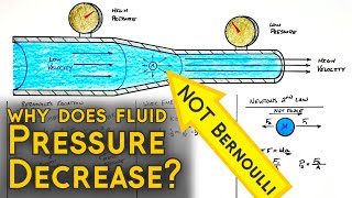
In hydraulic engineering, understanding the behavior of fluids in pipes and channels is crucial. The sectional analysis differentiates between open channel and pipeline flow, focusing on how hydraulic gradient lines align with the free surface in open channel flow. When water exits a pipe, it transitions to atmospheric pressure, causing the hydraulic gradient to coincide with the pipe outlet. The section explains mechanical energy losses through friction, leading to downward slopes in hydraulic and energy gradient lines. The effects of pumps and turbines illustrate the conversion of mechanical energy to fluid energy, underlining the importance of maintaining mechanical efficiency in flow systems. Exercises and examples provided throughout the section demonstrate the application of conservation laws and Bernoulli's equation, vital for analyzing flow in pipelines with sudden enlargements.
Youtube Videos

Audio Book
Dive deep into the subject with an immersive audiobook experience.
Introduction to Hydraulic Gradient in Open and Closed Channels
Chapter 1 of 5
🔒 Unlock Audio Chapter
Sign up and enroll to access the full audio experience
Chapter Content
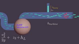
And okay, we are not discussing open channel flow heads, but in case of open channel flow, the hydraulic gradient lines coincide with the free surface of the liquid. Because there is no pressure head. So, whatever the water surface free surface, that what will be the hydraulic gradient line and the energy gradient lines will have included the velocity head above the free surface. That means, if you consider an open channel flow, this is the free surface. This free surface will be representing us hydraulic gradient line, and V²/2g of this, adding this velocity head, will get energy gradient line, okay, in case of open channel flow because there is no pressure head.
Detailed Explanation
In open channel flow, the hydraulic gradient line is essentially aligned with the free surface of the liquid because there is no pressure head (pressure from the liquid above is atmospheric). This means that the hydraulic gradient line, indicating the potential energy due to elevation, corresponds with the height of the water surface. The energy gradient line, which takes into account velocity, goes above this surface and represents the total energy of the liquid. This is derived from Bernoulli's principle where energy is distributed between potential energy (height) and kinetic energy (velocity).
Examples & Analogies
Imagine a river flowing smoothly; the surface of water represents the hydraulic gradient line, while an imaginary line above it represents the total energy of the moving water. When the water flows faster—like when flooding or heavy rain increases the flow—the energy gradient rises, showcasing how energy changes as flow conditions change.
Pressure and Hydraulic Gradient at Pipe Outlets
Chapter 2 of 5
🔒 Unlock Audio Chapter
Sign up and enroll to access the full audio experience
Chapter Content
Now, very basic things we should understand, whenever a pipe exits, that means flow is going out. The pressure head becomes atmospheric pressure, no doubt about that. And that is the reason, the hydraulic gradient lines coincide with the pipe outlet. So, when the pressure head becomes zero, that is what we said it, in case of open channel flow, when there is no pressure, is pressure is atmospheric pressure, that the surface becomes hydraulic gradient line.
Detailed Explanation
When fluid exits a pipe, the pressure it exerts essentially drops to atmospheric levels. This means the hydraulic gradient at the point where the fluid leaves the pipe coincides with atmospheric pressure. In essence, just like open channels where the surface level marks the hydraulic gradient line, the exit point of the pipe does the same. This concept helps in determining how fluids behave at junctions and their interaction with external pressure.
Examples & Analogies
Think of a garden hose pointed upward. When you release the nozzle, the water flows out at atmospheric pressure; this is similar to how hydraulic gradients drop to zero when exiting a pipe, serving as a natural endpoint for pressure gradients.
Energy Losses due to Mechanical Resistance
Chapter 3 of 5
🔒 Unlock Audio Chapter
Sign up and enroll to access the full audio experience
Chapter Content
Mechanical energy losses due to the frictional effects, which is converting from thermal energy, cause the energy gradient line and hydraulic gradient line to slope downwards in the direction of the flow. That is what I am trying to explain to you. There will be energy losses whenever you have flow systems.
Detailed Explanation
As fluid flows through a pipe, it encounters friction and resistance, which convert mechanical energy into thermal energy, ultimately dissipating energy in the form of heat. This leads to a downward slope in both the hydraulic and energy gradient lines in the direction of flow. Essentially, as water moves, it gets slower due to these losses, showing how energy is lost over distance.
Examples & Analogies
Imagine sliding down a slide. The longer you slide, the slower you go due to friction with the slide's surface. Similarly, as water flows through a pipe, it gradually loses energy due to resistance, resulting in an overall drop in energy levels as it moves.
Understanding Piezometric and Energy Gradient Lines
Chapter 4 of 5
🔒 Unlock Audio Chapter
Sign up and enroll to access the full audio experience
Chapter Content
But sometimes maybe the hydraulic gradient may not have the slope downward in direction of the flow. The gauge pressure of the is zero at the locations when the hydraulic gradient line intersects the fluids. The same things I think we are repeating; whatever we have said in the first point.
Detailed Explanation
In certain situations, while the energy gradient line is typically inclined due to losses, the hydraulic gradient might not always follow. When a hydraulic gradient line intersects with fluid, it indicates points of zero gauge pressure, meaning the fluid at this point doesn’t exert additional upward pressure. Understanding this distinction is key in predicting fluid behavior and energy transitions.
Examples & Analogies
Consider a water balloon that's filled just enough so it neither bulges outward (positive pressure) nor collapses inward (negative pressure). The point where the balloon is perfectly balanced in pressure can be compared to the hydraulic gradient line intersecting the fluid—it’s a balance point.
Pump and Turbine Systems
Chapter 5 of 5
🔒 Unlock Audio Chapter
Sign up and enroll to access the full audio experience
Chapter Content
As you know it, the pump transfers mechanical energy to fluid by rising pressures, ... Let us consider the problems when we generally use as an engineer having a pump and turbine systems.
Detailed Explanation
Pumps are devices used to increase the pressure of a fluid, thereby providing it with energy, allowing it to flow to higher elevations or across longer distances. Conversely, turbines extract energy from moving fluids, often converting kinetic energy to mechanical energy. Understanding this transfer of energy is crucial in system designs.
Examples & Analogies
Think of a bicycle pump. When you pump air, you increase the pressure in the tire, which helps the bike move faster. Similarly, pumps increase the pressure of fluids in pipes, while turbines act like windmill blades, converting the movement of air or water into usable energy.
Key Concepts
-
Hydraulic Gradient Lines: Align with the free surface in open flows and with atmospheric pressure at pipe outlets.
-
Energy Gradient Lines: Represent the total energy including velocity head, affected by frictional losses.
-
Bernoulli's Equation: Essential for analyzing flow behavior and energy conservation in hydraulic systems.
-
Impact of Pumps and Turbines: Convert mechanical energy into fluid energy and vice versa, affecting flow rates and system efficiencies.
Examples & Applications
A pump increases the pressure of fluid, allowing it to flow against gravity in a water supply system.
A turbine extract energy from flowing water to generate electricity in hydroelectric power plants.
Memory Aids
Interactive tools to help you remember key concepts
Rhymes
In pipes so tight, pressure takes flight, with pumps that push and turbines that might!
Stories
Imagine two walls of water, one high and one low. As they flow, a pump pushes the high one up while a turbine brings the low one down, dancing between pressure and flow. This is the life of our pipeline world!
Memory Tools
Remember P.E.V. - Potential, Energy, Velocity - the main components of Bernoulli!
Acronyms
B.O.P (Bernoulli's On Pressure) - helps you remember Bernoulli's principle connects pressure and energy.
Flash Cards
Glossary
- Hydraulic Gradient Line
A line that represents the total energy per unit weight of fluid in a flow system, including pressure and elevation.
- Energy Gradient Line
A line that accounts for the total energy (including kinetic and potential energy) available in the fluid along its flow path.
- Piezometer
A tube used for measuring the pressure of liquids at a certain point in the flow system.
- Pitot Tube
An instrument used to measure the velocity of a fluid by converting the kinetic energy of the fluid into potential energy.
- Bernoulli's Equation
An equation that describes the principle of conservation of energy for flowing fluids.
Reference links
Supplementary resources to enhance your learning experience.