
Bernoulli's Equation Applications
Enroll to start learning
You’ve not yet enrolled in this course. Please enroll for free to listen to audio lessons, classroom podcasts and take practice test.
Interactive Audio Lesson
Listen to a student-teacher conversation explaining the topic in a relatable way.
Hydraulic Gradient Lines
🔒 Unlock Audio Lesson
Sign up and enroll to listen to this audio lesson

Let’s start by talking about hydraulic gradient lines in open channel flow. Can anyone tell me what it represents?

Isn't it the level where the water surface meets the atmosphere?
Exactly! The hydraulic gradient line is at the free surface level because there is no pressure head. Now, when we add velocity head to this, what do we get?

The energy gradient line!
Well done! The energy gradient line includes the velocity head above the hydraulic gradient line. Remember my mnemonic, 'HE (Hydraulic Energy) above FL (Free Level)', which signifies the relationship!

What about in a pipe system?
Great question! In pipes, we measure the hydraulic gradient using tools like piezometers. So, can anyone summarize what we learned about hydraulic gradients?

The hydraulic gradient aligns with the free surface in open channels, and we can use piezometers in pipes.
Fantastic summary! We’ll continue to build on this.
Energy Gradient Lines
🔒 Unlock Audio Lesson
Sign up and enroll to listen to this audio lesson

Now, let’s delve into energy gradient lines. Who can remind me how energy gradient lines behave in systems with pressure heads?
They slope downwards due to energy losses!
Exactly! Mechanical energy losses result in a downward slope of energy gradient lines. So, in our systems, if we follow the flow, what does that tell us about energy?
It indicates there's a loss of energy as we move downstream?
Correct! It’s crucial to understand that energy losses can occur due to friction, which we often refer to as mechanical energy losses. Using the mnemonic 'MEL (Mechanical Energy Loss)', always keep that in your mind when thinking about energy gradients.
How does this relate to pumps and turbines?
That brings us to mechanical energy conversion! A pump adds mechanical energy to the fluid by increasing pressure, while a turbine extracts energy by decreasing pressure. Any thoughts on why understanding this relationship is important?
It helps us design efficient systems!
Exactly! We’ll explore that deeper in our next session.
Practical Applications
🔒 Unlock Audio Lesson
Sign up and enroll to listen to this audio lesson
Let’s relate what we’ve learned to real-world systems like pumps and turbines. Why do engineers need to apply Bernoulli's equation here?
To calculate how much energy we can gain or lose from the fluid!
Exactly! Bernoulli's equation is essential for determining the energy differences within these systems. First, let’s break down what happens in a pump.
It adds energy by increasing pressure!
Excellent! Conversely, what does a turbine do?
It extracts energy from the fluid.
Correct! So when we analyze these systems, we calculate efficiency using the ratio of input to output power.
So efficiency tells us how much energy loss occurs?
Exactly, it quantifies our losses and defines how effectively we convert energy. Always remember 'Lower Loss = Higher Efficiency'! Let's summarize what we learned.
We've discussed hydraulic and energy gradients, the effect of pumps and turbines, and the importance of calculating energy differences. All vital concepts for fluid mechanics!
Solving Fluid Dynamics Problems
🔒 Unlock Audio Lesson
Sign up and enroll to listen to this audio lesson
Now, how do we apply Bernoulli's equation and mass conservation in solving fluid problems?
We can use them to find pressures and velocities at different points in the system!
Correct! When analyzing flow, we sketch control volumes and streamlines. Can anyone explain what a control volume is?
It’s a defined region we analyze to apply conservation laws.
Exactly! And we often look at locations like pipe exits and entrances. What do we measure at these points?
Pressure and velocity!
Exactly, and let's not forget to identify assumptions, like steady flow! Remember the mnemonic 'SIMPLE' for 'Steady Incompressible Momentum Pressure Levels Equal'? Let’s put this into practice with an example exercise next week.
I feel more confident about solving fluid problems!
Great! Remember, understanding these core concepts is essential for effective problem-solving.
Pressure Changes in Flow Systems
🔒 Unlock Audio Lesson
Sign up and enroll to listen to this audio lesson
Let’s cap off our discussion by analyzing pressure changes and how it relates to the hydraulic gradient.
So, if the pressure is above the hydraulic gradient line, it's negative, right?
Correct! When pressure lies above the hydraulic gradient line, it's negative, and when below, it’s positive. Why is knowing this significant?
It helps us understand where flow might be unstable!
Exactly! It can indicate potential cavitation or flow separation. Always visualize how pressure interacts with our hydraulic lines. Let's end with a summary of terms—who can list a few?
Hydraulic gradient, energy gradient, and pressure differentials!
Great list! Remember these terms and their relationships to deepen your understanding of fluid mechanics. Our next session will be on problem-solving methods!
Introduction & Overview
Read summaries of the section's main ideas at different levels of detail.
Quick Overview
Standard
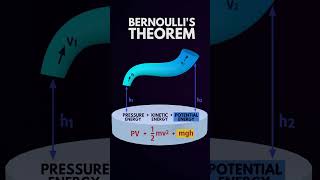
In this section, we examine how Bernoulli's equation applies to open channel and pipe flow, discussing concepts like hydraulic and energy gradient lines, and the effects of mechanical energy loss. We also delve into the practical implications of pressure differentials in various hydraulic systems, including pumps and turbines.
Detailed
Bernoulli's Equation Applications
This section emphasizes the applications of Bernoulli's equation in fluid dynamics, particularly in the contexts of open channel flow and pipe systems. The hydraulic gradient line aligns with the free surface of liquids in open channels, reflecting the absence of pressure head, while the energy gradient line incorporates velocity head.
In pipe systems, understanding hydraulic gradients becomes essential as mechanical energy losses due to friction lead to a downward slope in energy gradients. These principles manifest in practical engineering contexts, such as pump and turbine systems, where pressure is either increased or extracted from fluids. Bernoulli's equation helps analyze mechanical energy conversions in these systems, enabling engineers to determine energy differences crucial for effective design.
Furthermore, the section outlines how pressure changes relate to hydraulic gradient lines, emphasizing the importance of understanding when pressures are positive or negative in various sections of flow systems. By applying Bernoulli’s and mass conservation equations, students can solve hydraulic problems, employing methods such as drawing streamlines and defining control volumes to enhance their understanding. The challenges posed by inefficiencies in mechanical systems, like thermal and sound energy losses, are also highlighted, illustrating the real-world implications of theoretical fluid concepts.
Youtube Videos


Audio Book
Dive deep into the subject with an immersive audiobook experience.
Hydraulic Gradient and Free Surface in Open Channel Flow
Chapter 1 of 4
🔒 Unlock Audio Chapter
Sign up and enroll to access the full audio experience
Chapter Content
In open channel flow, the hydraulic gradient lines coincide with the free surface of the liquid because there is no pressure head. The free surface represents the hydraulic gradient line, while the energy gradient line includes the velocity head above the free surface. Therefore, in open channel flow, the hydraulic gradient line coinciding with the free surface indicates the absence of pressure head.
Detailed Explanation
In an open channel flow, like a river or canal, the level of the water (the free surface) is critical. This level serves as the hydraulic gradient line, meaning that at this point, there is no additional pressure. Instead, the only energy available is from the velocity of the water moving above this surface. Therefore, if you were to view the water flow at its surface, that would indicate the gradient of potential energy available in the water without any underlying pressure contributions.
Examples & Analogies
Think about a water slide at a theme park. The top of the slide represents the free surface (or hydraulic gradient line) of the water. As you slide down, the speed (velocity head) increases, but if there was no water pressure pushing you, your only source of potential energy is at the starting point of the slide, which corresponds to the water level at the top.
Pressure Head in Pipe Systems
Chapter 2 of 4
🔒 Unlock Audio Chapter
Sign up and enroll to access the full audio experience
Chapter Content
Whenever a pipe exits, the pressure head becomes atmospheric pressure. This leads the hydraulic gradient line to coincide with the pipe outlet as the pressure head becomes zero. Mechanical energy losses due to friction cause the energy gradient line and hydraulic gradient line to slope downwards in the direction of flow.
Detailed Explanation
In pipe systems, when water flows out of a pipe into the atmosphere, it is subject to atmospheric pressure, which means there is no 'stored' pressure head inside the pipe. As a result, the hydraulic gradient line aligns with the point of exit. Additionally, as fluid flows, it experiences energy losses—mainly due to friction, which reduces the total mechanical energy available, causing both the hydraulic and energy gradient lines to slope downward. This is critical for understanding behaviors in fluid systems, helping predict how energy is conserved or lost.
Examples & Analogies
Imagine a garden hose. When you let the water flow out without any devices to increase the pressure (like a pump), the water simply exits at atmospheric pressure. Over time, as you allow the water to flow, friction against the inner walls of the hose slows it down—this loss of energy is similar to how traffic slows down on a winding road. The steeper the slope of your hose (as with the gradient lines), the more noticeable this drop in speed becomes.
Energy Losses and Mechanical Efficiencies
Chapter 3 of 4
🔒 Unlock Audio Chapter
Sign up and enroll to access the full audio experience
Chapter Content
In flow systems, mechanical energy cannot be entirely converted from pumps or turbines due to various energy losses, including heat and sound. This results in a drop in efficiency when transforming one form of energy to another, often quantified through efficiency ratios comparing input and output power.
Detailed Explanation
When fluids move through systems involving pumps and turbines, they lose some of their mechanical energy to heat, sound, and other forms of dissipation. This inefficiency means that not all the energy supplied to the system results in useful work. Engineers often use efficiency ratios to understand these losses better. The ratio compares the useful output energy (or power) to the total input energy, indicating how effectively the system performs. Understanding this concept is crucial in designing efficient hydraulic systems.
Examples & Analogies
Consider a car engine. When you fill it with gasoline (input energy), not all that fuel results in motion (output energy) since some energy is lost as heat through friction and exhaust. Car manufacturers calculate the efficiency of engines to ensure they balance performance while minimizing energy waste. Similarly in hydraulic systems, measuring efficiency helps in recognizing how much 'fuel' (energy) is actually being used effectively.
Applications of Bernoulli’s Equation in Engineering
Chapter 4 of 4
🔒 Unlock Audio Chapter
Sign up and enroll to access the full audio experience
Chapter Content
In engineering, a pump transfers mechanical energy to fluid by raising its pressure, while a turbine extracts mechanical energy from the fluid by dropping its pressure. These systems illustrate the applications of Bernoulli's equation to calculate energy changes in moving fluids.
Detailed Explanation
The applications of Bernoulli's equation extend notably into engineering with devices like pumps and turbines. A pump increases the fluid's mechanical energy by raising its pressure, which results in a higher flow velocity and kinetic energy. Conversely, a turbine converts kinetic energy from a fast-moving fluid into usable mechanical energy, decreasing its pressure as it does. Analyzing these systems with Bernoulli’s equation enhances our understanding of fluid dynamics, helping engineers design efficient systems that move fluids effectively.
Examples & Analogies
Think about a fountain. The pump at the base pushes water upward, increasing its pressure and allowing it to shoot high into the air. When the water falls back down, the height it reaches, and the speed with which it splashes down demonstrate how energy transformations occur, reflecting principles of Bernoulli’s equation. The pump tirelessly converts energy from electrical to mechanical, while gravity and momentum transform it back down.
Key Concepts
-
Hydraulic Gradient Line: Represents the fluid's surface level and pressure head.
-
Energy Gradient Line: Represents total energy in the flow.
-
Bernoulli's Equation: Fundamental equation relating flow parameters.
-
Pressure Head: Height of fluid supported by pressure.
-
Losses: Energy dissipation in the system affecting performance.
-
Efficiency: Measure of how much useful energy is converted.
Examples & Applications
An open channel flow has a free surface where the hydraulic gradient line coincides with the surface.
In a pipe, when the hydraulic gradient equals the pipe outlet pressure, it indicates fluid is at atmospheric pressure.
Memory Aids
Interactive tools to help you remember key concepts
Rhymes
For every flow that's smooth and grand, hydraulic lines must always stand.
Stories
Imagine a city with a grand fountain. The water dances high, representing energy, always seeking the lowest point, just like the energy gradient in our fluid systems.
Memory Tools
Remember 'HELP' for Hydraulic Energy Loss Problems to address the key factors affecting flow.
Acronyms
Recall 'P-HEA' for Pressure, Head, Energy, and Area which are pivotal in calculating flow problems.
Flash Cards
Glossary
- Hydraulic Gradient Line
The line representing the free surface of a fluid in an open channel, indicating the pressure head.
- Energy Gradient Line
The line indicating the total energy (including kinetic and potential energy) of the fluid at various points in a flow system.
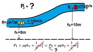
- Bernoulli's Equation
A fundamental principle in fluid dynamics that relates the pressure, velocity, and elevation in a flowing fluid.
- Pressure Head
The height of a fluid column that can be supported by the pressure at a given point.
- Piezometer
A device used to measure the potential energy within a fluid system by determining the fluid's pressure head.
- Losses
Energy losses in the flow due to friction or turbulence which result in reduced efficiency.
- Efficiency
The ratio of useful energy output to energy input in a mechanical system, expressed as a percentage.
Reference links
Supplementary resources to enhance your learning experience.