
Example Problems
Enroll to start learning
You’ve not yet enrolled in this course. Please enroll for free to listen to audio lessons, classroom podcasts and take practice test.
Interactive Audio Lesson
Listen to a student-teacher conversation explaining the topic in a relatable way.
Hydraulic and Energy Gradient Lines
🔒 Unlock Audio Lesson
Sign up and enroll to listen to this audio lesson

Today, we will discuss hydraulic gradient lines in open channel flows. Can anyone tell me what a hydraulic gradient line represents?

Isn't it the elevation of the water surface?
Exactly! In open channel flow, the hydraulic gradient line aligns with the free surface of the liquid because there’s no pressure head. Now, can anyone explain the difference between the hydraulic gradient line and the energy gradient line?

The energy gradient line includes both the hydraulic head and the velocity head.
Very good! Remember, the energy gradient adjusts for the kinetic energy present in the flow, showcasing total mechanical energy.

So, in a streamlined flow, that means the energy gradient line will always be above the hydraulic gradient line?
Correct! The difference gives us insight into energy losses in the system. Let’s summarize: the hydraulic gradient line shows the head due to the elevation of the fluid, while the energy gradient represents total energy including kinetic energy.
Pressure and Flow in Pipes
🔒 Unlock Audio Lesson
Sign up and enroll to listen to this audio lesson

Now, let’s shift our focus to pipes. When fluid exits a pipe into the atmosphere, what happens to the pressure?

The pressure becomes atmospheric, so the hydraulic gradient line coincides with the exit point.
Exactly! And why is it important to consider the pressure in relation to hydraulic gradients?
It helps us determine flow conditions and whether the pressure at any point is positive or negative.
That's right. Remember: if the pressure is above the hydraulic gradient line, it's positive; below it, it's negative.
So if I’m solving a pipe flow problem, I’d need to analyze where the pressure sits relative to that line!
Exactly, great insight! Always visualize your control volumes when solving pipe flow problems.
Pumps and Turbines
🔒 Unlock Audio Lesson
Sign up and enroll to listen to this audio lesson
Let’s discuss pumps and turbines. Who can tell me the difference in their functions?
Pumps add mechanical energy to the fluid, while turbines extract energy from it.
Exactly! Pumps increase pressure, while turbines decrease pressure to generate power. Why is this significant in system design?
It helps engineers determine where to place these devices, especially in power generation.
Correct! Understanding the transition of energy helps us optimize our systems and ensure efficiency.
And it’s crucial to consider efficiency factors since not all energy is transferred perfectly.
Exactly right! Efficiency can greatly affect the performance and cost of a fluid system.
Bernoulli's Equation Applications
🔒 Unlock Audio Lesson
Sign up and enroll to listen to this audio lesson
Now it’s time to apply what we’ve learned. Who knows how Bernoulli’s equation can be utilized in fluid flow problems?
You can use it to analyze flow between two points and calculate velocity changes with pressure differences.
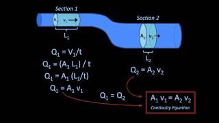
Right! For example, in a venturi tube, as the cross-sectional area decreases, what happens to the flow velocity?
It must increase because of conservation of mass.
Exactly! And we calculate that increase in velocity through Bernoulli’s equation. Let’s summarize: conservation of mass and energy principles are at play!
This visual pairing helps clarify how pressure and velocity interact in a flowing fluid!
Introduction & Overview
Read summaries of the section's main ideas at different levels of detail.
Quick Overview
Standard
In this section, we examine the behavior of fluids in open channels and pipes, introducing the concepts of hydraulic gradient lines, energy gradient lines, and mechanical energy losses. We further explore practical example problems to apply these principles, including the effects of pumps and turbines.
Detailed
In this section, we delve into the relationships between hydraulic gradients, energy gradients, and mechanical energy conversions in open channel flows and piping systems. The discussion highlights key concepts such as the significance of pressure head in determining hydraulic gradients and acknowledges that the hydraulic gradient coincides with atmospheric pressure at pipe exits. The narrative also explains how mechanical energy losses due to friction affect energy gradient slopes in fluid systems. The examples provided span practical engineering applications involving pumps and turbines, demonstrating how to use Bernoulli's equation and mass conservation to solve real-world problems. Emphasis is placed on the importance of understanding flow classifications as well as applying theoretical equations to derive useful relationships in fluid mechanics.
Youtube Videos


![Power and Energy: Example 1: Part 1 [Fluid Mechanics #32]](https://img.youtube.com/vi/6PM15ec7oMs/mqdefault.jpg)


Audio Book
Dive deep into the subject with an immersive audiobook experience.
Understanding Open Channel Flow
Chapter 1 of 10
🔒 Unlock Audio Chapter
Sign up and enroll to access the full audio experience
Chapter Content
And okay, we are not discussing about open channel flow heads, but in case of open channel flow, the hydraulic gradient lines coincides with the free surface of the liquid okay. Because there is no pressure head. So, whatever the water surface free surface, that what will be hydraulic gradient line and the energy gradient lines will have a included the velocity head above the free surface.
Detailed Explanation
In open channel flow, the hydraulic gradient (which represents the change in energy head per unit length) aligns with the free surface of the liquid. This occurs because there isn’t any pressure head in open channels—the energy relative to vertical elevation and velocity is what we consider. Thus, when observing the flow at the surface level, the hydraulic gradient simply follows that level, while the energy gradient accounts for the kinetic energy related to fluid motion, indicated by the velocity head.
Examples & Analogies
Imagine a river flowing smoothly. The surface of the river represents the hydraulic gradient, and as you throw a ball into the river, it represents the kinetic energy—just like the water moves quickly due to its velocity.
Hydraulic Gradient in Pipes
Chapter 2 of 10
🔒 Unlock Audio Chapter
Sign up and enroll to access the full audio experience
Chapter Content
But in case of the pipes, we can have a piezometer to measure it, what could be the hydraulic gradient lines. Energy gradient line to measure it we need to have a pitot tube to compute what will be these things.
Detailed Explanation
In contrast to open channels, when dealing with pipes, we utilize instruments such as piezometers to measure the hydraulic gradient. A piezometer shows us the pressure head at any point along the pipe, which is necessary for understanding how fluid moves through it. To measure the energy gradient, we use a pitot tube, which helps us assess the kinetic energy of the fluid by measuring the velocity head related to that flow.
Examples & Analogies
Think of this like a water slide at a theme park. You can see where the water level is (like the hydraulic gradient) by looking at the height of the water against the side of the slide, and you can gauge how fast the water is moving (the energy gradient) through special openings in the slide that show the speed of water flowing.
Pressure Changes in Fluid Flow
Chapter 3 of 10
🔒 Unlock Audio Chapter
Sign up and enroll to access the full audio experience
Chapter Content
Now very basic things we should understand it, whenever a pipe exit, that means flow is going out. The pressure head becomes atmospheric pressure, no doubt about that. And that is the reason, the hydraulic gradient lines coincidence with the pipe outlet.
Detailed Explanation
An important principle of fluid dynamics is that when fluid exits a pipe, the corresponding pressure head at the exit point equals atmospheric pressure. This equality means the hydraulic gradient at the outlet aligns with the pipe’s opening because there is no more pressure to push the fluid beyond the atmosphere at this point. As a hydrostatic condition is established, the pressure head effectively drops to zero.
Examples & Analogies
Consider a garden hose. When you remove the nozzle to let water freely flow out, the water starts flowing with no additional pressure—just gravity and atmospheric pressure propel it. The flow's energy and behavior change noticeably when you do this, similar to what happens when fluid exits a pipe.
Mechanical Energy Losses
Chapter 4 of 10
🔒 Unlock Audio Chapter
Sign up and enroll to access the full audio experience
Chapter Content
Mechanical energy losses due to the frictional effects, which is converting from thermal energy, the causes the energy gradient line, hydraulic gradient line, to a slope downwards in the directions of the flow.
Detailed Explanation
In fluid systems, flow encounters friction, which transfers some mechanical energy into thermal energy, resulting in energy losses. These losses mean that as fluid flows through a pipe, the energy gradient does slope downward along the flow direction due to decreasing energy availability as frictional forces impede motion.
Examples & Analogies
Imagine sliding down a slide. If the slide is smooth, you'll go down quickly, but if it’s rough with many bumps, you'll lose speed. The same happens with fluid in pipes, where friction reduces its energy, making it harder for fluid to maintain speed.
Pressure Above and Below Hydraulic Gradient Line
Chapter 5 of 10
🔒 Unlock Audio Chapter
Sign up and enroll to access the full audio experience
Chapter Content
Pressure in a flow sections lies above the hydraulic gradient line is negative. Pressure in a section when the lies below the hydraulic gradient line is positive and the negative that is the difference what we get it.
Detailed Explanation
This statement refers to the relationship of pressure to the hydraulic gradient line. If a section's pressure is above this line, it indicates a negative gauge pressure—meaning the pressure is lower than atmospheric pressure. Conversely, if it is beneath the line, it signifies a positive gauge pressure, where the fluid is under greater pressure than the atmosphere. This difference is critical for understanding fluid behavior under varying conditions.
Examples & Analogies
Think of a balloon. When the internal pressure is greater than that of the outside environment, the balloon stays inflated (positive gauge pressure). If you poke a hole in it, the pressure drops, showing negative gauge pressure as the air rushes out, mimicking how fluid pressure behaves along these hydraulic lines.
Applications of Pumps and Turbines
Chapter 6 of 10
🔒 Unlock Audio Chapter
Sign up and enroll to access the full audio experience
Chapter Content
Now, let us consider is the problems when we generally use as a engineer having a pump and turbine systems. As you know it, the pump is transfer from mechanical energy to fluid by rising pressures, okay. Transfer the mechanical energy to a fluid. So, fluid gains the energy because of the pumping systems by rising its pressures.
Detailed Explanation
Pumps and turbines are essential components in fluid systems. A pump increases the mechanical energy of a fluid by elevating its pressure, allowing the fluid to flow through systems against resistance. In contrast, turbines extract energy from a fluid, reducing its pressure, which is useful in applications like hydropower generation. Both systems work based on the fundamental principles of energy conservation and transformation.
Examples & Analogies
Picture a bicycle pump: as you push the handle, you compress the air inside, increasing its pressure. This is similar to what a pump does to a fluid. On the other hand, when you release the bike pump and air rushes out, you’re letting energy escape, like how a turbine works with moving water to generate power.
Efficiency of Pumps and Turbines
Chapter 7 of 10
🔒 Unlock Audio Chapter
Sign up and enroll to access the full audio experience
Chapter Content
Pressure itself is not a form of energy as we all say that, it is just a flow energy or storage potential energy per unit volume that is the pressures.
Detailed Explanation
While pressure is crucial in determining the energy within a fluid, it is important to recognize that pressure alone does not equate to energy. Instead, pressure contributes to the total energy available in fluid systems, which includes kinetic and potential energy components. Understanding this distinction helps analyze the efficiency of pumps and turbines. High-efficiency systems effectively convert and manage these energy forms for required outcomes.
Examples & Analogies
Consider a water tank at an elevated position. The water possesses potential energy due to its height, but the pressure within the tank essentially merely facilitates flow; the real energy is realized when you let the water flow downward or through pipes.
Bernoulli’s Principle in Practice
Chapter 8 of 10
🔒 Unlock Audio Chapter
Sign up and enroll to access the full audio experience
Chapter Content
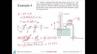
If I have a dam, the reservoir, water is going through a turbine and generators, coming out at the three, then it is related to the tail end reservoir.
Detailed Explanation
Visualizing a dam helps illustrate Bernoulli’s principle effectively. Water at the highest elevation within a dam possesses potential energy due to gravity. As it flows downward toward the turbines, this potential energy is converted into kinetic energy, causing the turbines to generate mechanical energy. The interconnected reservoirs represent different elevation levels, demonstrating how energy transforms through gravitational potential and kinetic aspects as energy moves through the system.
Examples & Analogies
Think of a downhill roller coaster. The car at the top has high potential energy, but as it descends, that energy converts into speed (kinetic energy), allowing it to traverse both further down and across the track—similarly to how water moves through a dam.
Example Problem: Venturi Tube
Chapter 9 of 10
🔒 Unlock Audio Chapter
Sign up and enroll to access the full audio experience
Chapter Content
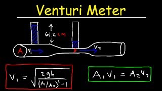
A constriction in a pipe will cause the velocity to rise and the pressure to fall at section 2 in the throat. The pressure difference is a measure of the flow rate through the pipe. The smoothly necked-down system shown in figure is called a venture tube.
Detailed Explanation
This problem focuses on the use of a Venturi tube, which takes advantage of the principle of flow continuity and Bernoulli’s equation. As fluid flows into a constricted section of the tube (the throat), its velocity increases, leading to a reduction in pressure. Measuring this pressure difference allows engineers to infer information about the fluid’s flow rate through the pipe, a critical factor in design and analysis.
Examples & Analogies
Picture a garden hose with your thumb partially blocking the end. The water speed increases, shooting out farther because of the constriction from your thumb—similar to what happens in a Venturi tube, where flow speed rises through narrowing and pressure drops correspondingly.
Conclusion on Fluid Flow Dynamics
Chapter 10 of 10
🔒 Unlock Audio Chapter
Sign up and enroll to access the full audio experience
Chapter Content
Let me conclude this lecture with the sense of balance of organ systems...
Detailed Explanation
The provided insights into fluid dynamics and engineering principles highlight various critical scenarios, from understanding pressure and energy interactions to practical applications like pumps and turbines. Through continued experimentation, evaluation, and application, these principles allow engineers to navigate and solve complex problems effectively.
Examples & Analogies
Like balancing on a bicycle requires understanding shifts in weight and steering, mastering fluid dynamics requires balancing various energy and pressure factors within systems—essentially ensuring a smooth operation through nuanced knowledge.
Key Concepts
-
Pressure Head: The height of a column of liquid that can be supported by a given fluid's pressure.
-
Hydraulic Gradient: The slope of the hydraulic gradient line in relation to the fluid head.
-
Energy Losses: Loss of mechanical energy in a fluid system due to friction and other factors.
Examples & Applications
Example 1: Calculating velocity increase and pressure decrease in a venturi tube using Bernoulli's equation.
Example 2: Assessing how pump placement influences flow and energy transformation in a pipeline setup.
Memory Aids
Interactive tools to help you remember key concepts
Rhymes
At the top, the water's flow, Hydraulic heights make it glow.
Stories
Imagine a pump on a water slide, pushing you up to ride the tide.
Memory Tools
P.E.V. - Potential Energy + Velocity Energy = Total Energy in Flow.
Acronyms
H.E.L.P. - Hydraulic Energy Losses Propel.
Flash Cards
Glossary
- Hydraulic Gradient Line
A line that represents the hydraulic head in an open channel flow.
- Energy Gradient Line
A line showing the total mechanical energy (potential + kinetic) in a fluid system.
- Bernoulli's Equation
A principle that describes the conservation of energy in fluid flow, relating pressure, height, and velocity.
- Pump
A device that adds mechanical energy to a fluid.
- Turbine
A device that extracts energy from flowing fluid.
Reference links
Supplementary resources to enhance your learning experience.