
Hydraulic Gradient Lines
Enroll to start learning
You’ve not yet enrolled in this course. Please enroll for free to listen to audio lessons, classroom podcasts and take practice test.
Interactive Audio Lesson
Listen to a student-teacher conversation explaining the topic in a relatable way.
Introduction to Hydraulic Gradient Lines
🔒 Unlock Audio Lesson
Sign up and enroll to listen to this audio lesson

Today, we'll talk about hydraulic gradient lines. Can anyone tell me what they think a hydraulic gradient line is?

Is it a line showing the pressure of water in a pipe?
That's a good start! A hydraulic gradient line represents the level of hydraulic head in a flow system. In open channel flow, it's actually the same as the water surface. This means no pressure head exists at that point.

So, in an open channel, the water surface is also the hydraulic gradient line?
Exactly! We often represent it as a straight line matching the free surface. Now, what about in piping systems? How do we measure it there?

With a piezometer!
Yes! Piezometers allow us to measure pressure heads, which help us define the hydraulic gradient line in a closed system.
To remember this, think of it as 'pressure measuring devices - piezometers establish heights!'
In summary, the hydraulic gradient line in open channels is equivalent to the free water surface. In closed systems, we measure this line with piezometers.
Energy Loss and Gradient Lines
🔒 Unlock Audio Lesson
Sign up and enroll to listen to this audio lesson

Now that we understand hydraulic gradient lines, let's discuss energy gradient lines. Who can tell me how they differ from hydraulic gradient lines?

I think energy gradient lines account for both pressure and velocity heads, right?
Yes! The energy gradient line includes the velocity head, which is calculated using V²/2g. This is crucial for understanding energy losses due to friction or other factors.
So, more energy means a higher energy gradient line?
Correct! However, mechanical energy losses—like friction—can cause the energy gradient line to slope downward relative to the hydraulic gradient line. Why do you think this happens?
Because energy is lost as the fluid flows?
Exactly! As the fluid moves, it experiences friction, which reduces its energy. Remember: Energy losses change the slope of the gradient lines. A mnemonic to recall could be 'Friction descends flow!'
In conclusion, energy gradient lines incorporate both pressure and velocity, and their slope can indicate energy loss in the system.
Applying Hydraulic Gradient Lines
🔒 Unlock Audio Lesson
Sign up and enroll to listen to this audio lesson
Let’s apply what we've learned to real-world systems, such as pumps and turbines. Can someone explain their roles in influence hydraulic gradient lines?
Pumps increase pressure in a fluid?
Exactly right! Pumps convert mechanical energy into fluid energy, raising pressure and changing the hydraulic gradient line! Now, how about turbines?
Turbines decrease the pressure and extract energy, right?
Correct! Turbines do the opposite of pumps. They decrease fluid pressure, indicated by a drop in the hydraulic gradient line. Think of turbines reducing 'flow pressure.'
So both have different effects on hydraulic gradient lines?
Absolutely! This shows how energy transfers and conversions impact hydraulic systems. Always remember, pumps pressure up, while turbines pressure down!
In summary, pumps increase the hydraulic gradient line, while turbines decrease it.
Gradient Lines in Practical Examples
🔒 Unlock Audio Lesson
Sign up and enroll to listen to this audio lesson
Now, let’s look at some practical examples of hydraulic gradient lines in action. Can anyone give an instance where we've seen this concept applied?
In a water supply pipeline!
Excellent! In a water supply pipeline, we measure pressure and elevation to ensure adequate flow. The hydraulic gradient line will help ensure we maintain enough pressure throughout the pipeline.
What happens if there's a leak?
Good question! A leak will lower the pressure, altering the hydraulic gradient line. This could lead to insufficient flow downstream. It's vital to monitor these lines in real systems!
What about in the design of irrigation systems?
Great point! Engineers use hydraulic gradient lines to make sure all fields receive enough water. It is crucial for efficient irrigation management.
In summary, we see hydraulic gradient lines play a critical role in various systems, ranging from water supply to irrigation, ensuring proper function and efficiency.
Introduction & Overview
Read summaries of the section's main ideas at different levels of detail.
Quick Overview
Standard
The section explains the concept of hydraulic gradient lines, noting that in open channel flow, they coincide with the free surface due to the absence of pressure head, while in pipe flow, piezometric measurements assist in determining these lines. The section also explains the implications of mechanical energy losses and introduces pumping and turbine systems as practical applications of these principles.
Detailed
Detailed Summary
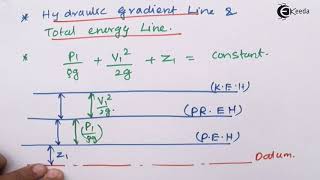
Hydraulic gradient lines are pivotal in understanding fluid mechanics, especially in distinguishing how energy is distributed in different flow scenarios. In open channel flow, the hydraulic gradient line aligns with the liquid's free surface since there is no pressure head involved. In contrast, for pipe flow, piezometric heads measured using devices like piezometers determine the hydraulic gradient lines.
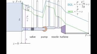
Energy gradient lines extend above the hydraulic gradient lines to accommodate the velocity head calculated by the equation V²/2g, where V is the flow velocity and g is the acceleration due to gravity.
Moreover, hydraulic gradient lines intersect with areas of pressure, allowing engineers to identify negative gauge pressures when above the line and positive when below. The energy losses observed due to mechanical friction result in a discernible downward slope of both gradient lines in the direction of flow. Additionally, the section emphasizes the importance of understanding how pumps increase fluid mechanical energy while turbines extract energy, further illustrating the concepts introduced through Bernoulli's equations and mechanical energy conservation.
Youtube Videos
![Hydraulic and Energy Grade Line ? with animation [ HGL and EGL ]](https://img.youtube.com/vi/moI4DQNirAw/mqdefault.jpg)


Audio Book
Dive deep into the subject with an immersive audiobook experience.
Hydraulic and Energy Gradient Lines in Open Channels
Chapter 1 of 7
🔒 Unlock Audio Chapter
Sign up and enroll to access the full audio experience
Chapter Content
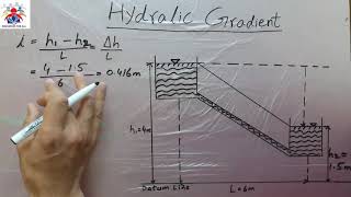
And okay, we are not discussing about open channel flow heads, but in case of open channel flow, the hydraulic gradient lines coincides with the free surface of the liquid okay. Because there is no pressure head. So, whatever the water surface free surface, that what will be hydraulic gradient line and the energy gradient lines will have a included the velocity head above the free surface.
Detailed Explanation
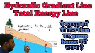
In open channel flow, the hydraulic gradient line (HGL) represents the potential energy of the fluid due to elevation and pressure. Since, in an open channel, the pressure head is zero (the air pressure is acting on the free surface), the HGL coincides with the free surface of the water. The energy gradient line (EGL), however, includes the velocity head, which accounts for the kinetic energy of the flowing water above this free surface, indicating that as the velocity of the fluid increases, the total energy of the fluid system also increases.
Examples & Analogies
Think of a river flowing gently: the water surface is the HGL. If we were to add a paddle boat moving through the water, the speed of the boat represents the velocity head, which increases the total energy of the water at that point.
Hydraulic Gradient Lines in Pipes
Chapter 2 of 7
🔒 Unlock Audio Chapter
Sign up and enroll to access the full audio experience
Chapter Content
But in case of the pipes, we can have a piezometer to measure it, what could be the hydraulic gradient lines. Energy gradient line to measure it we need to have a pitot tube to compute what will be these things.
Detailed Explanation
In closed conduits or pipes, the hydraulic gradient line can be measured using instruments like piezometers, which measure the pressure head of the fluid in the pipe. The energy gradient line can be determined using a pitot tube, which measures the dynamic pressure (kinetic energy) of the fluid flow, allowing for calculations of the total energy in the system. The pressure head contributes to the total energy and makes it necessary for engineers to understand how pressure and energy lines interact in pipe systems.
Examples & Analogies
Imagine a water supply system in a building. The water pressure at various points can be measured with piezometers attached to the pipes to ensure proper supply levels, while pitot tubes may be used to analyze how much more energy is needed to move the water faster through the system.
Atmospheric Pressure and Hydraulic Gradient Lines
Chapter 3 of 7
🔒 Unlock Audio Chapter
Sign up and enroll to access the full audio experience
Chapter Content
Now very basic things we should understand it, whenever a pipe exit, that means flow is going out. The pressure head becomes atmospheric pressure, no doubt about that. And that is the reason, the hydraulic gradient lines coincidence with the pipe outlet.
Detailed Explanation
When liquid exits a pipe, the pressure inside the pipe at that exit point equalizes to atmospheric pressure, which is considered the reference level (zero pressure head). This results in the hydraulic gradient line aligning with the outlet of the pipe. Any fluid under atmospheric pressure behaves in the same way as the fluid in an open channel, further reinforcing the concept that the pressure head determines the hydraulic gradient in both situations.
Examples & Analogies
Consider a garden hose: when you turn off the water, the flow stops, and the pressure at the end of the hose equalizes with the outside air. The water level in the hose at the exit corresponds with the atmospheric pressure.
Energy Gradients and Mechanical Energy Losses
Chapter 4 of 7
🔒 Unlock Audio Chapter
Sign up and enroll to access the full audio experience
Chapter Content
Mechanical energy losses due to the frictional effects, which is converting from thermal energy, the causes the energy gradient line, hydraulic gradient line, to a slope downwards in the directions of the flow.
Detailed Explanation
As fluid flows through a pipe, it experiences friction and turbulence, which lead to mechanical energy losses. This results in a downward slope in both the energy gradient line (EGL) and the hydraulic gradient line (HGL) in the direction of flow. The energy lost due to friction means that the total energy available to do work decreases as you move along the pipe, hence the gradient sloping downwards reflects this loss.
Examples & Analogies
Picture riding a bicycle uphill; as you pedal against resistance (friction), you lose energy, making it harder to maintain speed. Similarly, in a pipe, as fluid moves, it encounters resistance caused by interactions with the pipe walls, leading to energy losses.
Understanding Gauge Pressure and Its Significance
Chapter 5 of 7
🔒 Unlock Audio Chapter
Sign up and enroll to access the full audio experience
Chapter Content
The gauge pressure of the is zero at the locations when the hydraulic gradient line intersect the fluids.
Detailed Explanation
Gauge pressure is defined as the pressure relative to atmospheric pressure. When the hydraulic gradient line intersects the fluid level (indicating that the hydraulic gradient is zero), it implies that there is no excess pressure above atmospheric (or gauge pressure is zero). Understanding this intersection helps engineers determine points in the system where pressure is critical, such as ensuring enough energy in the fluid flow.
Examples & Analogies
Consider using a pressure gauge to monitor a tire; when the gauge reads zero, the air pressure inside the tire is equal to the atmospheric pressure outside. This is a crucial check to verify the tire’s condition.
Engineered Systems with Pumps and Turbines
Chapter 6 of 7
🔒 Unlock Audio Chapter
Sign up and enroll to access the full audio experience
Chapter Content
Now, let us consider is the problems when we generally use as an engineer having a pump and turbine systems. As you know it, the pump is transfer from mechanical energy to fluid by rising pressures, okay.
Detailed Explanation
Pumps and turbines are essential components in fluid mechanistic systems. Pumps increase the pressure of fluids by converting mechanical energy into hydraulic energy, effectively pushing the fluid through systems. Conversely, turbines extract energy from flowing liquids, which leads to a drop in fluid pressure. This interaction illustrates the key functions of both equipment in maintaining energy balance within fluid systems.
Examples & Analogies
Think of a waterwheel. As water flows over it, the wheel spins, harnessing the water's energy (like a turbine), while pumping water from a river uphill (like a pump) to be distributed throughout a field.
Role of Efficiency in Fluid Systems
Chapter 7 of 7
🔒 Unlock Audio Chapter
Sign up and enroll to access the full audio experience
Chapter Content
Pressure itself is not a form of energy as we all say that, it is just a flow energy or storage potential energy per unit volume that is the pressures.
Detailed Explanation
Pressure acts as an indicator of potential energy within a fluid system rather than representing energy itself. In fluid mechanics, pressure provides a measure of how much energy can potentially be retrieved from the fluid flow. Understanding this principle helps engineers design more efficient systems by optimizing how energy is stored and released within fluid parameters.
Examples & Analogies
Imagine a car's gas tank. The fuel (analogous to the fluid) represents stored energy. Pressure in the fuel lines allows for efficient delivery of that energy to the engine, helping the car operate effectively.
Key Concepts
-
Hydraulic Gradient Line: Represents the fluid's hydraulic head and coincides with the free surface in open channels.
-
Energy Gradient Line: Accounts for both pressure and velocity heads, indicating the total energy available in a fluid flow system.
-
Piezometer: An instrument used to measure fluid pressure in pipes, helping to determine the hydraulic gradient.
-
Mechanical Energy Loss: The energy losses due to frictional forces in a fluid system, affecting gradient lines.
Examples & Applications
- A hydraulic gradient line in a river visually indicates where the water surface lays, affecting flow velocity and energy.
- In a water treatment plant, engineers use piezometers to determine the hydraulic gradient line as part of flow management.
Memory Aids
Interactive tools to help you remember key concepts
Rhymes
Gradient lines show where pressure does climb, in channels and pipes, they signify flow time.
Stories
Imagine a river, with water so bright, its surface reflects the hydraulic gradient line's height.
Memory Tools
Remember PE – Pressure Equals; Hydraulic lines reflect pressure levels.
Acronyms
HGL – Hydraulic Gradient Line; a motto to recall the term's significance!
Flash Cards
Glossary
- Hydraulic Gradient Line
A line representing the hydraulic head in a flow system; in open channels, it coincides with the liquid's free surface.
- Energy Gradient Line
A line that accounts for both pressure and velocity heads and indicates potential mechanical energy in fluid flow.
- Piezometer
A device used to measure the pressure head of a fluid in a closed system.
- Velocity Head
A term representing gravitational potential energy of fluid in motion, calculated as V²/2g.
- Mechanical Energy Losses
Energy lost in a fluid system, primarily due to friction and other forms of resistance.
Reference links
Supplementary resources to enhance your learning experience.