
Types of Resonant Circuits
Interactive Audio Lesson
Listen to a student-teacher conversation explaining the topic in a relatable way.
Introduction to Series Resonant Circuits
🔒 Unlock Audio Lesson
Sign up and enroll to listen to this audio lesson

Today we're discussing series resonant circuits. Can anyone tell me what makes a resonant circuit essential in high-frequency applications?

Is it because they allow for maximum current flow at a specific frequency?
Exactly! In a series resonant circuit, at resonance, the impedance becomes purely resistive, allowing maximal current flow. Remember, they consist of inductors and capacitors connected in series. We can summarize this with the mnemonic 'SIR' - Series Impedance Resistance.

What's the resonant frequency formula again?
Good question! The resonant frequency, f0, is given by f0 = 1/(2π√(LC)). Let’s break that down - L is inductance and C is capacitance.

So, if we know L and C, we can find f0 for our design?
That's right! And how about the quality factor, Q?

It represents the ratio of f0 over the bandwidth, right?
Exactly, and it indicates the selectivity and sharpness of resonance. Remember, a high Q means a narrow bandwidth.
In summary, series resonant circuits minimize impedance and are critical in applications needing high current flow.
Introduction to Parallel Resonant Circuits
🔒 Unlock Audio Lesson
Sign up and enroll to listen to this audio lesson

Now, let's move on to parallel resonant circuits. Who can explain how they differ from series circuits?
In parallel, the inductor and capacitor are connected side by side, right?
Correct! This configuration leads to a very high impedance at the resonant frequency, which essentially maximizes the circuit's impedance. Can anyone tell me what happens to the current here?
The current is minimized, since the circuit 'blocks' the signal more effectively.
That's a perfect insight! Again, we use the same formula for resonant frequency, f0 = 1/(2π√(LC)). So, the resonant frequency doesn’t change. What about the bandwidth and Q factor here?
Parallel circuits have bandwidth based on the parallel resistance, right?
Exactly! The Q factor here is given by Q = RL/√(L/C). A high Q indicates better selectivity and performance for filters and tuning applications.
To summarize, parallel resonant circuits maximize impedance at resonance and are used in applications requiring minimal current flow.
Applications of Resonant Circuits
🔒 Unlock Audio Lesson
Sign up and enroll to listen to this audio lesson
Let's discuss real-world applications of these resonant circuits. Can anyone think of where you would utilize series resonant circuits?
In RF amplifiers, to boost signals at specific frequencies!
Exactly! Series circuits excel in boosting signals in applications like oscillators. And what about parallel resonant circuits?
They’re used for tuning in radios, right? To filter and select specific frequencies.
Correct! Parallel configurations work great for tuning and filtering because of their high impedance. Another mnemonic to remember these applications could be 'FILTER' - Frequencies In, Low Energy, Tuning Easy and Resonance!
That’s really handy! So both types have distinct applications?
Exactly! Each type offers unique benefits suited for different scenarios in wireless communications, ensuring efficient signal transfer.
Introduction & Overview
Read summaries of the section's main ideas at different levels of detail.
Quick Overview
Standard
In this section, we explore the main characteristics of series and parallel resonant circuits. These circuits, consisting of inductors and capacitors, exhibit distinct behaviors at resonance, including impedance characteristics, resonant frequency equations, and Quality Factor (Q) implications that are crucial for applications in RF and HF engineering.
Detailed
Types of Resonant Circuits
The section introduces two main types of resonant circuits found in RF and HF applications: Series Resonant Circuits and Parallel Resonant Circuits. Both circuits utilize inductors (L) and capacitors (C), yet they behave differently at resonance, impacting their applications and design.
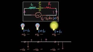
Series Resonant Circuit
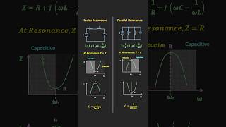
In a series resonant circuit, components are connected in series with a signal source. At resonance, the circuit’s reactance is ideally nullified, resulting in the total impedance equaling only the resistance (R). The resonant frequency (f0) of the series circuit is determined by the formula:
f0 = 1/(2π√(LC)). The bandwidth (BW) and Quality Factor (Q) of this configuration are tightly coupled, influencing selectivity and efficiency in applications such as oscillators.
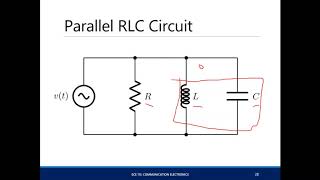
Parallel Resonant Circuit
Conversely, a parallel resonant circuit places the inductor and capacitor in parallel to the signal source. Here, the circuit exhibits very high impedance at resonance, minimizing current. Similar to series circuits, the resonant frequency (f0) remains governed by the same formula:
f0 = 1/(2π√(LC)). However, the bandwidth is defined according to the parallel resistance, and the Q factor characterizes the sharpness of resonance effects, essential for tuning and filtering applications.
In summary, understanding these resonant circuit types is vital for designing efficient RF and HF systems.
Youtube Videos

Audio Book
Dive deep into the subject with an immersive audiobook experience.
Overview of Resonant Circuits
Chapter 1 of 9
🔒 Unlock Audio Chapter
Sign up and enroll to access the full audio experience
Chapter Content
There are two primary types of resonant circuits: Series Resonant Circuits and Parallel Resonant Circuits. Both configurations involve inductors (L) and capacitors (C) and exhibit unique behaviors at resonance.
Detailed Explanation
Resonant circuits can be categorized mainly into two types: Series and Parallel. These circuits use inductors (which store energy in a magnetic field) and capacitors (which store energy in an electric field). Their arrangement leads to different behaviors when they reach resonance—a state where the circuit either allows maximum current (in series) or limits current flow (in parallel).
Examples & Analogies
Think of series and parallel resonant circuits as two types of racing tracks. On a series track (like a straight road), cars move freely without much resistance, speeding up until they reach their peak. In contrast, a parallel track (like a winding road) can slow down vehicles because of multiple routes, only allowing a few to go fast at any given time.
Series Resonant Circuit
Chapter 2 of 9
🔒 Unlock Audio Chapter
Sign up and enroll to access the full audio experience
Chapter Content
A series resonant circuit consists of an inductor and a capacitor connected in series with a signal source. At resonance, the impedance of the circuit is purely resistive, and the circuit allows maximum current to flow.
Detailed Explanation
In a series resonant circuit, the inductor and capacitor are connected in a line with the signal source. At the circuit's resonant frequency, their reactances (oppositions to current flow) cancel each other out, leading to a situation where the overall impedance—resistance to AC current—is minimized. This means that this type of circuit can let the maximum amount of current flow through it, making it ideal for applications that require strong signals.
Examples & Analogies
Consider a water pipe system with two valves (the inductor and capacitor). When the pressure (current) is just right (at resonance), the valves work perfectly together, allowing water to flow freely without any blockages (minimum impedance).
Impedance at Resonance in Series Circuit
Chapter 3 of 9
🔒 Unlock Audio Chapter
Sign up and enroll to access the full audio experience
Chapter Content
At resonance, the inductive reactance XL and capacitive reactance XC are equal and opposite, resulting in zero net reactance. The total impedance Z of the circuit is simply the resistance R of the resistor (or equivalent resistance in case of practical components).
Detailed Explanation
In a series resonant circuit, both the inductive and capacitive reactances can be measured. When the circuit reaches its resonant frequency, these two values become equal. This equality means that their combined effect results in no opposition to AC current—hence zero net reactance exists, and the impedance of the circuit is solely resistive, reducing to simply R (the resistance).
Examples & Analogies
You can think of this scenario like opposing forces in sports. Imagine a tug of war where two equally strong teams pull in opposite directions (the inductive and capacitive reactances). When they are perfectly balanced, the rope remains still, similar to how the circuit has zero net reactance at resonance.
Resonant Frequency in Series Resonant Circuit
Chapter 4 of 9
🔒 Unlock Audio Chapter
Sign up and enroll to access the full audio experience
Chapter Content
The resonant frequency f0 of a series LC circuit is given by: f0 = 1 / (2π√(LC))
Detailed Explanation
The resonant frequency is a critical aspect of a series resonant circuit because it guarantees maximum current flow. This frequency is determined by the values of the inductor (L) and capacitor (C) in the circuit. The formula indicates that as the inductance or capacitance increases, the resonant frequency decreases, and vice versa.
Examples & Analogies
Think of tuning into a radio station. The frequency you set on your radio acts like the resonant frequency. If you want to listen to a specific station (maximum current flow), you need to dial it to the correct frequency. If you are too high or too low, you won't get the clearest sound (not resonating).
Bandwidth and Quality Factor (Q) in Series Circuit
Chapter 5 of 9
🔒 Unlock Audio Chapter
Sign up and enroll to access the full audio experience
Chapter Content
The bandwidth (BW) of the resonant circuit is the range of frequencies around f0 where the circuit can operate effectively. It is determined by the resistance R. The Quality Factor (Q) measures the selectivity or sharpness of the resonance.
Detailed Explanation
The bandwidth of the series resonant circuit indicates how wide the frequency range is that can produce a strong response. It’s directly influenced by the resistance in the circuit—lower resistance typically results in a wider bandwidth. The Quality Factor (Q) assesses how 'sharp' or selective the resonance is: a higher Q indicates a narrower bandwidth and thus more precise tuning capabilities.
Examples & Analogies
Imagine tuning a guitar. A guitar string has certain frequencies that it resonates at (like a specific note). If you pluck it gently, it produces a clear note (high Q, narrow bandwidth), but if you hit it harder or accidentally dampen it, other frequencies emerge (wider bandwidth). Just as a musician aims for a clean note, engineers aim for a sharp resonance in circuits.
Parallel Resonant Circuit
Chapter 6 of 9
🔒 Unlock Audio Chapter
Sign up and enroll to access the full audio experience
Chapter Content
A parallel resonant circuit consists of an inductor and a capacitor connected in parallel with a signal source. At resonance, the impedance of the circuit becomes very high, and the current through the circuit is minimized.
Detailed Explanation
In a parallel resonant circuit, the inductor and capacitor are connected side by side with the signal source. Unlike the series circuit, at resonance, the total impedance of this setup becomes very high. This high impedance means that not much current flows through the circuit during resonance, making it useful for applications where minimal current is desired.
Examples & Analogies
Think of a parallel resonant circuit like multiple lanes on a highway. As more cars (current) enter, the overall flow can become congested. If the right conditions are met (like a traffic signal), traffic can bottleneck, making it harder for cars to pass (high impedance), which is similar to how current flow is minimized at resonance.
Impedance at Resonance in Parallel Circuit
Chapter 7 of 9
🔒 Unlock Audio Chapter
Sign up and enroll to access the full audio experience
Chapter Content
At resonance, the inductive reactance and capacitive reactance are equal and opposite, resulting in infinite impedance in the ideal case. In a practical scenario, the impedance is limited by the resistance of the inductor and any losses in the circuit.
Detailed Explanation
In an ideal parallel resonant circuit, the inductive reactance and capacitive reactance cancel each other out completely, leading to extremely high impedance (theoretically infinite). In reality, some resistance in the inductor and losses will prevent it from being completely infinite, but the overall impedance at resonance will still be significantly high compared to non-resonant conditions.
Examples & Analogies
Think about a perfect balance beam. In an ideal situation, a perfectly balanced beam (where two people weigh the same) would stay level forever (infinite impedance). However, if one person loses some weight (resistance and loss), they may gradually want to tip to one side.
Resonant Frequency in Parallel Resonant Circuit
Chapter 8 of 9
🔒 Unlock Audio Chapter
Sign up and enroll to access the full audio experience
Chapter Content
The resonant frequency f0 of a parallel LC circuit is the same as in the series circuit: f0 = 1 / (2π√(LC))
Detailed Explanation
Just as in series resonant circuits, the resonant frequency for parallel circuits is influenced by the values of the inductor and capacitor. This means that the same formula applies, reaffirming that both types of circuits resonate at the same frequency based on their L and C values.
Examples & Analogies
Returning to the radio example, whether you are tuning into a nearby station or not, the resonance frequency remains the same because the characteristics of the circuit (the L and C values) dictate it, similar to how tuning into the same radio station yields the same frequency regardless of the type of radio you are using.
Bandwidth and Quality Factor (Q) in Parallel Circuit
Chapter 9 of 9
🔒 Unlock Audio Chapter
Sign up and enroll to access the full audio experience
Chapter Content
The bandwidth is determined by the parallel resistance R, and the Q factor is defined as: Q = f0 / BW.
Detailed Explanation
Aside from the differences in current flow, parallel resonant circuits also measure bandwidth and Q factor. The bandwidth indicates the range of frequencies the circuit can efficiently operate, while the Q factor measures how selective (sharp) the resonance is during that operation. In parallel circuits, the Q factor would indicate how precise you can narrow the selection of frequencies to obtain desired outputs.
Examples & Analogies
Think of catching butterflies in a net. A high Q factor is like having a very fine net with tiny holes, allowing you to catch only the most specific type of butterflies (very selective resonance). If the net is broader with larger holes (low Q), you'll catch more types of butterflies, but not as specific (wider bandwidth).
Key Concepts
-
Series Resonant Circuits: Allow maximum current flow and have purely resistive impedance at resonance.
-
Parallel Resonant Circuits: Allow high impedance and minimize current flow at resonance.
-
Resonant Frequency (f0): Determined by the formula f0 = 1/(2π√(LC)).
-
Quality Factor (Q): Indicates selectivity and is crucial for the design of filters and oscillators.
-
Bandwidth (BW): Defines the effective range of frequencies around the resonant frequency.
Examples & Applications
A series resonant circuit can be employed in an RF amplifier to selectively enhance signal strength at a specific radio frequency.
A parallel resonant circuit can be used in a radio tuner, allowing users to filter desired stations while ignoring others.
Memory Aids
Interactive tools to help you remember key concepts
Rhymes
In series circuits, current flows bold, at resonance, a story told.
Stories
Imagine a race between currents; series circuits let them run free, while parallel circuits hold them back. Just like a crowded party where some dance while others sit.
Memory Tools
Remember 'SIR' for Series Impedance Resistance and 'FILTER' for frequency selection. These will help you recall the main concepts.
Acronyms
P.I. for Parallel Impedance (maximized), indicating a parallel resonant circuit's behavior.
Flash Cards
Glossary
- Series Resonant Circuit
A circuit where inductors and capacitors are connected in series, allowing maximum current flow at resonance.
- Parallel Resonant Circuit
A circuit where inductors and capacitors are connected in parallel, resulting in high impedance and minimal current flow at resonance.
- Resonant Frequency (f0)
The frequency at which the inductive and capacitive reactances are equal and cancel each other out.
- Quality Factor (Q)
A measure of the selectivity and sharpness of resonance; it indicates how well a circuit can select particular frequencies.
- Bandwidth (BW)
The range of frequencies around the resonant frequency where the circuit operates effectively.
- Impedance (Z)
The measure of resistance a circuit presents to the flow of alternating current.
Reference links
Supplementary resources to enhance your learning experience.