
Step 3: Calculate the Quality Factor and Bandwidth
Interactive Audio Lesson
Listen to a student-teacher conversation explaining the topic in a relatable way.
Understanding Quality Factor (Q)
🔒 Unlock Audio Lesson
Sign up and enroll to listen to this audio lesson

Today, we'll explore the Quality Factor, or Q, which indicates how sharp or selective a circuit's resonance is. Can anyone tell me why selectivity is important in resonant circuits?

Maybe because we want to target specific frequencies?
Exactly! The sharper the resonance, the better the circuit is at filtering out unwanted frequencies. Now, who can tell me how Q is calculated in a series resonant circuit?

Is it Q = f0/BW?
Correct! That means if we want a higher Q, we need a narrower bandwidth. Remember that as a mnemonic: 'High Q, Narrow BW.'

What's an example of where we'd need a high Q?
Great question! High Q circuits are essential in applications like selective filters. To summarize, a high Q indicates better selectivity, which is valuable for applications requiring precise frequency targeting.
Calculating Bandwidth (BW)
🔒 Unlock Audio Lesson
Sign up and enroll to listen to this audio lesson

Next, let's discuss bandwidth, which is crucial for understanding how resonant circuits perform across different frequencies. Can someone remind me how bandwidth is defined for a series resonant circuit?

I think it's BW = R/L?
Correct! And for parallel resonant circuits, it’s a bit different. We say that BW is also influenced by the parallel resistance. Remember that bandwidth helps us see the range of frequencies where the circuit will work effectively.
Can you give me an example where we want to calculate the bandwidth?
Definitely! In a radio receiver, you’d need to measure BW to ensure you pick up your desired station without interference from others. To wrap up, always remember that bandwidth gives us practical insight into a circuit’s effectiveness.
Application of Q and BW in Design
🔒 Unlock Audio Lesson
Sign up and enroll to listen to this audio lesson
Finally, let’s talk about how we apply the Q and bandwidth calculations in the design of resonant circuits. Why do you think knowing these factors is important in circuit design?
Because it helps us select the right components?
Exactly! Choosing the correct L, C, or R values helps us achieve our desired f0, Q, and BW. When designing, if you require a narrower bandwidth, you would want to choose a high Q. So if you need to design a filter for clear audio, you would aim for high selectivity.
How would that affect our component choices?
Good question! You might select a larger inductor for higher Q or a lower resistance to narrow the bandwidth. In conclusion, understanding Q and bandwidth provides the foundation for effective circuit design.
Introduction & Overview
Read summaries of the section's main ideas at different levels of detail.
Quick Overview
Standard
In this section, we delve into the calculation of the Quality Factor (Q) and bandwidth (BW) for both series and parallel resonant circuits. Understanding these calculations is crucial for optimizing the performance of resonant circuits in various applications.
Detailed
Step 3: Calculate the Quality Factor and Bandwidth
Overview
Calculating the Quality Factor (Q) and bandwidth (BW) is fundamental in determining the performance and effectiveness of resonant circuits, which are used widely in RF and HF applications. In this section, we will explore how to calculate these parameters for both series and parallel resonant circuits, which demonstrate different behaviors at resonance.
Key Concepts
- Quality Factor (Q): The Quality Factor measures the sharpness or selectivity of the resonance. A higher Q indicates a narrow bandwidth and higher selectivity, which is particularly valuable in applications such as selective filters.
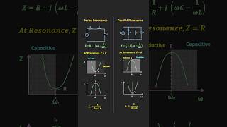
- For Series Resonant Circuits:\
$$Q = \frac{f_0}{BW} = \frac{\sqrt{L/C}}{R}$$ -
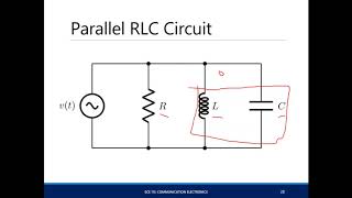
For Parallel Resonant Circuits:\
$$Q = \frac{f_0}{BW} = \frac{R}{\sqrt{L/C}}$$ - Bandwidth (BW): Bandwidth corresponds to the range of frequencies around the resonant frequency where the circuit can operate effectively. This parameter is influenced by the resistance in the circuit:
- For Series Resonant Circuits:\
$$BW = \frac{R}{L}$$ - For Parallel Resonant Circuits:\
The parallel resistance also determines the bandwidth and works inversely with the Quality Factor.
Conclusion
Calculating the Quality Factor and bandwidth is essential for the design, analysis, and functionality of resonant circuits, affecting their performance in real-world applications like filtering, tuning, and signal amplification.
Youtube Videos


Audio Book
Dive deep into the subject with an immersive audiobook experience.
Understanding Quality Factor (Q)
Chapter 1 of 3
🔒 Unlock Audio Chapter
Sign up and enroll to access the full audio experience
Chapter Content
The Quality Factor (Q) measures the selectivity or sharpness of the resonance:
Q=f0/BW=√(L/C)/R
Detailed Explanation
The Quality Factor, often abbreviated as Q, is an important metric when discussing resonant circuits. It helps in understanding how selective a circuit is at its resonant frequency. A high Q value indicates that the circuit will only allow signals close to the resonant frequency to pass through, while a lower Q implies a wider range of frequencies can interact with the circuit. The formula to calculate Q involves the resonant frequency (f0), bandwidth (BW), the inductance (L), the capacitance (C), and the resistance (R). Specifically, Q is calculated by dividing the resonant frequency by the bandwidth, with the formula expressed as Q = f0/BW = √(L/C)/R. Essentially, you can think of Q as a measure of how 'sharp' or 'narrow' the focus of the circuit is on its resonance frequency.
Examples & Analogies
Imagine you're at a concert aiming to listen to a particular song. If the sound system has a high quality factor, it'll enhance that specific song and block out the surrounding noise, much like how a high Q factor in a resonant circuit allows only a narrow range of frequencies to pass through clearly.
Calculating Bandwidth (BW)
Chapter 2 of 3
🔒 Unlock Audio Chapter
Sign up and enroll to access the full audio experience
Chapter Content
The bandwidth (BW) of the resonant circuit is the range of frequencies around f0 where the circuit can operate effectively. It is determined by the resistance R.
BW=R/L
Detailed Explanation
Bandwidth, denoted as BW, is the spectrum or range of frequencies that a resonant circuit can effectively operate within, surrounding its resonant frequency (f0). The bandwidth is inversely related to the resistance in the circuit; as the resistance increases, the bandwidth also increases. This means a higher resistance allows for a greater range of frequencies to be processed by the circuit. The formula to calculate the bandwidth is BW = R/L, showing that, in simple terms, the greater the resistance, the more frequency range the circuit can handle effectively. Thus, knowing the resistance and inductance enables you to understand how wide the operational frequency range of the circuit will be.
Examples & Analogies
Think of bandwidth in the context of a highway. If a highway has a lot of lanes (high resistance), more cars (frequencies) can travel concurrently, making the traffic smoother over a wider area. If the highway has fewer lanes (low resistance), then only a select few cars can move through easily, reflecting a narrower bandwidth.
Interconnection Between Q and BW
Chapter 3 of 3
🔒 Unlock Audio Chapter
Sign up and enroll to access the full audio experience
Chapter Content
A high Q factor indicates a narrow bandwidth and high selectivity.
Detailed Explanation
The relationship between Quality Factor (Q) and bandwidth (BW) is crucial for understanding the performance of resonant circuits. When a circuit exhibits a high Q, it means it is very selective, focusing tightly on a specific frequency. As a result, the bandwidth becomes narrow, allowing very few frequencies outside of that resonance frequency to affect the circuit's operation. This can be beneficial for applications where you want to minimize interference from surrounding signals. Conversely, if you lower the Q factor, the bandwidth broadens, meaning the circuit becomes less selective and more frequencies are allowed to influence it.
Examples & Analogies
Consider a spotlight in a dark room. A narrow beam (high Q) lights only a small area (narrow bandwidth), allowing you to focus on something specific like a book on a table. If you widen the beam (lower Q), you illuminate more of the room (wider bandwidth), but you lose detail on the specific object of interest. This illustrates how the Q and bandwidth interact with respect to focus and selectivity.
Key Concepts
-
Quality Factor (Q): The Quality Factor measures the sharpness or selectivity of the resonance. A higher Q indicates a narrow bandwidth and higher selectivity, which is particularly valuable in applications such as selective filters.
-
For Series Resonant Circuits:\
-
$$Q = \frac{f_0}{BW} = \frac{\sqrt{L/C}}{R}$$
-
For Parallel Resonant Circuits:\
-
$$Q = \frac{f_0}{BW} = \frac{R}{\sqrt{L/C}}$$
-
Bandwidth (BW): Bandwidth corresponds to the range of frequencies around the resonant frequency where the circuit can operate effectively. This parameter is influenced by the resistance in the circuit:
-
For Series Resonant Circuits:\
-
$$BW = \frac{R}{L}$$
-
For Parallel Resonant Circuits:\
-
The parallel resistance also determines the bandwidth and works inversely with the Quality Factor.
-
Conclusion
-
Calculating the Quality Factor and bandwidth is essential for the design, analysis, and functionality of resonant circuits, affecting their performance in real-world applications like filtering, tuning, and signal amplification.
Examples & Applications
In an RF filter circuit designed for a specific frequency, the bandwidth can be calculated as BW = R/L, helping to ensure that only desired frequencies pass through.
For a series resonant circuit with a high Q factor, such as in a tuner for a radio, selective frequencies are amplified while minimizing interference from adjacent channels.
Memory Aids
Interactive tools to help you remember key concepts
Rhymes
Bandwidth wide, Q be low; Q is high if narrow's your flow.
Stories
Imagine a radio tuner trying to catch a smooth sound. The tuner adjusts to narrow in on one station, just like Quality Factor targeting only specific frequencies.
Memory Tools
To remember the Q formula, think: 'Quickly Find Bandwidth as Q.'
Acronyms
Use Q-Band
for Quality and Band for Bandwidth
to remember their relationship.
Flash Cards
Glossary
- Quality Factor (Q)
A measure of the sharpness or selectivity of resonance in a resonant circuit, calculated as Q = f0/BW.
- Bandwidth (BW)
The range of frequencies over which a resonant circuit operates effectively, defined as BW = R/L for series circuits.
- Resonant Frequency (f0)
The frequency at which the resonance occurs, calculated from the values of inductance and capacitance.
Reference links
Supplementary resources to enhance your learning experience.