
Step 3: Calculate the Bandwidth and Quality Factor
Interactive Audio Lesson
Listen to a student-teacher conversation explaining the topic in a relatable way.
Understanding Bandwidth
🔒 Unlock Audio Lesson
Sign up and enroll to listen to this audio lesson

Today, we'll focus on bandwidth, an essential concept in resonant circuits. Can anyone tell me what bandwidth is?

Isn't it the range of frequencies around the resonant frequency?
Exactly! The bandwidth indicates how effectively the circuit can operate around its resonant frequency. For a series resonant circuit, we calculate bandwidth using the formula BW = R/L. Why do you think resistance affects the bandwidth?

Maybe because more resistance allows the circuit to handle a wider range of frequencies?
That's a great observation! More resistance means more energy can be dissipated, leading to a wider bandwidth overall. Remember, a wider bandwidth means the circuit is less selective.

So, if we want to design a filter with a very specific frequency, we must manage the bandwidth carefully?
Right! Remember, if the Q factor is high, the bandwidth will be narrow and the circuit will be more selective. Let's recap: Bandwidth is determined by resistance and inductance.
Quality Factor (Q)
🔒 Unlock Audio Lesson
Sign up and enroll to listen to this audio lesson

Now that we've covered bandwidth, let's dive into the quality factor, commonly called the Q factor. Can someone explain what Q signifies in a resonant circuit?

Q measures how sharp the resonance of the circuit is, right?
Spot on! The formula for Q in a series circuit is Q = f0/BW. A higher Q value indicates sharper response. What does this mean for a practical application?
It means the circuit can be tuned very precisely to a certain frequency, which is essential for filters!
Exactly! So, if you're designing a selective filter, you'd aim for a high Q factor. Also, remember that the Q factor in parallel circuits is Q = R/√(L/C), which highlights how resonance changes in different configurations.
So in that case, we can either adjust resistance to change the Q or play with the capacitance and inductance?
Correct! Balancing these elements allows you to design for either narrow or wide bandwidths, depending on your needs.
Applying Bandwidth and Q in Circuit Design
🔒 Unlock Audio Lesson
Sign up and enroll to listen to this audio lesson
So, how would bandwidth and Q factor guide us in designing an actual resonant circuit for RF applications?
If I want a circuit to only amplify a specific radio frequency, I’d need a high Q for a narrow bandwidth.
Right! And in this case, you'd need an appropriate balance of L and C, along with a suitable resistor value to achieve that Q. What’s one potential drawback of a high Q factor?
It could make the circuit too sensitive and could possibly miss other nearby frequencies?
Exactly! High selectivity is excellent, but it can lead to problems with signal detection if nearby frequencies are also important. Always consider the application!
So, it seems like a balance is key in circuit design.
Well said! Always strive for balance and clarity in your designs when considering bandwidth and quality factor.
Introduction & Overview
Read summaries of the section's main ideas at different levels of detail.
Quick Overview
Standard
In this section, we explore how to calculate the bandwidth and quality factor of series and parallel resonant circuits. These calculations are vital for understanding how effectively a circuit can operate around its resonant frequency and play a significant role in applications such as filters and oscillators.
Detailed
Step 3: Calculate the Bandwidth and Quality Factor
In the design of resonant circuits, calculating the bandwidth and quality factor is critical for optimizing circuit performance.
Bandwidth
The bandwidth (BW) is defined as the range of frequencies around the resonant frequency at which the circuit can effectively operate. For a series resonant circuit, the relationship is given by:
\[ BW = \frac{R}{L} \]
Where R is the resistance and L is the inductance. This formula indicates that higher resistance will lead to a wider bandwidth, as more energy can be dissipated at various frequencies.
Quality Factor (Q)
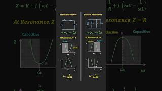
The quality factor (Q) is a measure of how selective or sharp the resonance is, usually presented in two forms. For a series resonant circuit, it is defined as:
\[ Q = \frac{f_0}{BW} = \frac{L}{CR} \]
Where \( f_0 \) is the resonant frequency, C is the capacitance, and R is the resistance. A higher Q indicates a narrow bandwidth, which is particularly useful in applications requiring selectivity, such as RF filters.
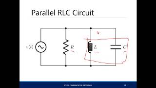
In parallel resonant circuits, while the resonant frequency remains the same, the bandwidth and Q factor definitions differ:
\[ Q = \frac{f_0}{BW} = \frac{R}{\sqrt{L/C}} \]
Here, achieving a desired bandwidth can be accomplished by adjusting the resistance, affecting the circuit's selectivity at resonance.
Understanding these parameters is essential for effective circuit design and is applied in various applications, such as filters, oscillators, and impedance matching networks.
Youtube Videos


Audio Book
Dive deep into the subject with an immersive audiobook experience.
Understanding Bandwidth
Chapter 1 of 2
🔒 Unlock Audio Chapter
Sign up and enroll to access the full audio experience
Chapter Content
- The bandwidth (BW) of the resonant circuit is the range of frequencies around f0 where the circuit can operate effectively. It is determined by the resistance R.
- BW=R/L
Detailed Explanation
Bandwidth refers to the range of frequencies where the resonant circuit can function well. Specifically, it represents the span between the upper and lower frequency limits where the circuit still performs effectively. The bandwidth is inversely related to the value of resistance (R) and the inductance (L) of the circuit. This means that if you have a higher resistance, the bandwidth will be wider, allowing the circuit to operate over a larger frequency range.
Examples & Analogies
Think of bandwidth like the width of a highway. A wider highway can accommodate more cars traveling in different directions (frequencies) without congestion (loss of signal clarity). If the highway has to deal with tight turns (high resistance), then fewer cars can travel through efficiently, which is similar to a narrow bandwidth.
Quality Factor (Q)
Chapter 2 of 2
🔒 Unlock Audio Chapter
Sign up and enroll to access the full audio experience
Chapter Content
- The Quality Factor (Q) measures the selectivity or sharpness of the resonance:
- Q=f0/BW=L/CR
- A high Q factor indicates a narrow bandwidth and high selectivity.
Detailed Explanation
The Quality Factor (Q) is a key parameter that denotes how selective a resonant circuit is. A high Q indicates that the circuit is very selective, meaning it will resonate sharply at a particular frequency and suppress signals outside of that frequency range. It is calculated by the formula Q = f0 / BW, where f0 is the resonant frequency and BW is the bandwidth. Thus, a high Q corresponds to a narrow bandwidth, which can be advantageous in filtering applications.
Examples & Analogies
You can think of the Q factor like a spotlight vs. a floodlight. A spotlight (high Q) focuses intensely on a small area (specific frequency), while a floodlight (low Q) illuminates a wide area but with less intensity. If you want to focus on a precise detail in a performance (specific frequency selectivity), you'll want a spotlight—just like you want a high Q factor in certain electronic applications.
Key Concepts
-
Bandwidth: The range of frequencies effective for circuit operation around the resonant frequency.
-
Quality Factor (Q): Indicates how selective a resonant circuit is; higher Q means sharper resonance.
-
Resonant Frequency (f0): The frequency at which the circuit is most responsive, determined by L and C.
-
Inductive and Capacitive Reactance: Responses of an inductor and capacitor to AC, crucial for resonance calculations.
Examples & Applications
In a series LC circuit with L = 10mH and R = 5 ohms, the bandwidth can be calculated as BW = R/L = 5/0.01 = 500 Hz.
For a parallel LC circuit with a desired resonant frequency of 2 MHz, and a Q factor of 100, the necessary resistance can be adjusted to vary the bandwidth to fit design requirements.
Memory Aids
Interactive tools to help you remember key concepts
Rhymes
To find the bandwidth in our electronic land, divide R by L, that’s the plan.
Stories
Imagine tuning a radio. If you turn the dial too wide (high bandwidth), you might miss your favorite station. A narrow range (high Q) helps you hit the spot precisely—just like finding a treasure!
Memory Tools
Think of 'BDC' - Bandwidth is determined by Resistance and Capacitance.
Acronyms
Remember Q-BAND
Quality and Bandwidth are navigated in design.
Flash Cards
Glossary
- Bandwidth (BW)
The range of frequencies around the resonant frequency at which a circuit can operate effectively.
- Quality Factor (Q)
A measure of the selectivity or sharpness of resonance in a circuit, with higher values indicating narrower bandwidth and greater selectivity.
- Resonant Frequency (f0)
The frequency at which a circuit resonates, determined by the values of its inductance and capacitance.
- Inductive Reactance (XL)
The opposition to the flow of alternating current caused by inductors, increasing with frequency.
- Capacitive Reactance (XC)
The opposition to the flow of alternating current caused by capacitors, decreasing with frequency.
Reference links
Supplementary resources to enhance your learning experience.