
Resonant Frequency - 3.2.1.2
Interactive Audio Lesson
Listen to a student-teacher conversation explaining the topic in a relatable way.
Introduction to Resonant Frequency
🔒 Unlock Audio Lesson
Sign up and enroll to listen to this audio lesson

Today, we’re diving into resonant frequency, which occurs in resonant circuits when inductive and capacitive reactances are equal. Can anyone tell me why this is important in circuit design?

Because it allows for maximum energy transfer, right?
Exactly! This is crucial in applications like tuning circuits and filters. Now, what are the formulas we need to remember for calculating this frequency?

It’s f0 = 1/(2π√(LC))!
Correct! Remember to balance L and C to find the right frequency. Let’s summarize: resonant frequency is where XL meets XC, and the formula is vital for our designs. Can anyone explain the consequence of resonating frequencies?

We get maximum current in series circuits!
Perfect! And in parallel circuits?

The impedance becomes very high, minimizing current.
Great job, everyone! Remember, understanding these principles is key to designing effective circuits.
Impedance and Quality Factor
🔒 Unlock Audio Lesson
Sign up and enroll to listen to this audio lesson

Let’s move on to impedance. In a series resonant circuit, what happens to impedance at resonant frequency?
It becomes purely resistive, right?
Exactly! At resonance, Z = R. Now, what about bandwidth and the quality factor? Why is it important?
The bandwidth tells us the operational frequency range, and the Q factor indicates how selective the circuit is!
Right! To calculate bandwidth, we use BW = R/L, and for Q factor, we have Q = f0/BW. Which circuits value more precision?
Series circuits, since they are used for filtering!
Yes! Precision in timing can distinguish signals clearly. Let’s summarize our points: Impedance at resonance, bandwidth, and quality factor all play key roles in design.
Application of Resonant Circuits
🔒 Unlock Audio Lesson
Sign up and enroll to listen to this audio lesson
Now, let’s explore applications! How are resonant circuits used in real life?
In filters for audio equipment!
Exactly! They help remove unwanted frequencies. Can anyone provide another example?
Oscillators for radio signals!
Right again! Resonant circuits help keep the signal clean. Why do you think we care about quality factor in these applications?
A higher Q means better selectivity in what frequencies get through!
Absolutely! Knowing all this allows engineers to make informed choices in their designs. What would you say is the main takeaway from today?
Understanding how resonance improves performance in circuits!
Spot on! Great engagement today!
Introduction & Overview
Read summaries of the section's main ideas at different levels of detail.
Quick Overview
Standard
In this section, we explore resonant frequency in series and parallel resonant circuits, highlighting the significance of impedance, bandwidth, and quality factor (Q). Understanding resonant frequency is critical in designing circuits for applications like filtering, tuning, and amplification.
Detailed
Overview of Resonant Frequency
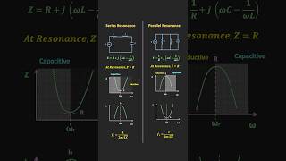
Resonant frequency is a fundamental concept in resonant circuits, occurring when the inductive (XL) and capacitive (XC) reactances balance each other out. This results in specific behaviors in both series and parallel configurations:
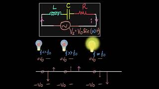
- Series Resonant Circuits: Here, at the resonant frequency (f0), the total impedance of the circuit reduces to the resistance (R), enabling maximum current flow. The formula for resonant frequency is given by:
$$ f_0 = \frac{1}{2\pi\sqrt{LC}} $$
where L represents inductance and C represents capacitance.
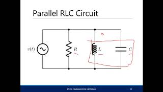
- Parallel Resonant Circuits: In these circuits, at resonant frequency, the impedance becomes significantly high, ideally tending toward infinity, thus minimizing current. This also utilizes the same resonant frequency formula as the series configuration, emphasizing the principle of frequency balancing.
- Bandwidth and Quality Factor (Q): The bandwidth around the resonant frequency indicates operational frequency range, determined by circuit resistance, and the quality factor reflects the sharpness of resonance. A higher Q indicates a narrower bandwidth, enhancing selectivity in applications.
Youtube Videos
Audio Book
Dive deep into the subject with an immersive audiobook experience.
Resonant Frequency Definition
Chapter 1 of 3
🔒 Unlock Audio Chapter
Sign up and enroll to access the full audio experience
Chapter Content
The resonant frequency f₀ of a series LC circuit is given by:
f₀ = \frac{1}{2 \pi \sqrt{L C}}
Where:
- L is the inductance,
- C is the capacitance.
Detailed Explanation
The resonant frequency, denoted as f₀, is the frequency at which a resonance circuit naturally oscillates. It depends on two key components: inductance (L) of the inductor and capacitance (C) of the capacitor in the circuit. The formula shows that the resonant frequency is inversely proportional to the square root of the product of these two values. This means that higher inductance or capacitance will lower the resonant frequency, and vice versa.
Examples & Analogies
Imagine a swing. The heavier the swing (analogous to higher inductance), the slower it will swing back and forth. Conversely, if you have a lighter swing (lower inductance), it will swing more quickly. This is similar to how the values of L and C determine the frequency at which the circuit will resonate.
Impedance at Resonance
Chapter 2 of 3
🔒 Unlock Audio Chapter
Sign up and enroll to access the full audio experience
Chapter Content
At resonance, the inductive reactance Xₗ and capacitive reactance Xᶜ are equal and opposite, resulting in zero net reactance. The total impedance Z of the circuit is simply the resistance R of the resistor (or equivalent resistance in case of practical components).
Zₗₑₛₒₙₐₙ𝒸ₑ = R.
Detailed Explanation
When a series resonant circuit is at its resonant frequency, the effects of the inductor and capacitor balance each other out, meaning that their reactances (Xₗ for inductors and Xᶜ for capacitors) are equal in magnitude but opposite in sign. This leads to a situation where the total reactance is zero, and the circuit behaves purely resistively. The result is a minimal impedance, allowing maximum current flow through the circuit when it resonates.
Examples & Analogies
Think of a seesaw. If both sides are of equal weight (representing equal reactance), the seesaw stays balanced. When balanced, the seesaw can go up and down smoothly, similar to how maximum current flows through the circuit when it is at resonance.
Bandwidth and Quality Factor (Q)
Chapter 3 of 3
🔒 Unlock Audio Chapter
Sign up and enroll to access the full audio experience
Chapter Content
The bandwidth (BW) of the resonant circuit is the range of frequencies around f₀ where the circuit can operate effectively. It is determined by the resistance R.
BW = \frac{R}{L}.
The Quality Factor (Q) measures the selectivity or sharpness of the resonance:
Q = \frac{f₀}{BW} = \frac{L/C}{R}. A high Q factor indicates a narrow bandwidth and high selectivity.
Detailed Explanation
Bandwidth is an important parameter that defines how much range in frequencies the circuit can effectively respond to around its resonant frequency. The formula shows that bandwidth is influenced by the resistance in the circuit. The Quality Factor (Q) tells us how 'sharp' or selective the resonance is; a higher Q indicates that the circuit will respond to a narrower range of frequencies. This means if Q is high, the circuit is very selective, allowing only specific frequencies to pass through.
Examples & Analogies
Imagine tuning a radio to find your favorite station. A radio with a high Q factor is much like having a fine-tuning knob that lets you precisely adjust to the right frequency without picking up too much interference or noise from adjacent stations. In contrast, a lower Q factor would be like having a coarse knob that could easily pick up multiple channels at once.
Key Concepts
-
Resonant Frequency: The specific frequency where reactances cancel, allowing maximum energy transfer.
-
Impedance: The measure of opposition in a circuit, pivotal for understanding how current flows.
-
Bandwidth: Defines effective operational frequency ranges in circuits.
-
Quality Factor: Indicates the sharpness of resonance crucial for signal selectivity.
Examples & Applications
A radio receiver utilizes resonant frequency to filter out unwanted signals, enhancing audio clarity.
Oscillators in a microwave circuit depend on resonant frequency to generate microwave signals accurately.
Memory Aids
Interactive tools to help you remember key concepts
Rhymes
When L and C together meet, the frequency’s labeled complete; energy flows with ease, as impedance drops to please.
Stories
Imagine a DJ tuning into the right station. With perfect frequency alignment, the sound is crystal clear, and every beat resonates, showing how resonant circuits make radio magic happen by selecting the right signals, leaving out noisy interference.
Memory Tools
Remember the acronym 'RIB-Q': 'R' for Resonance, 'I' for Impedance, 'B' for Bandwidth, 'Q' for Quality Factor. This can help recall the fundamental aspects of resonant circuits.
Acronyms
Use 'R-F-Q' to denote 'Resonant Frequency Quality'. This aids in reminding the connections between resonant frequency and its characteristics.
Flash Cards
Glossary
- Resonant Frequency
The frequency at which the inductive and capacitive reactances in a resonant circuit are equal and opposite, maximizing energy transfer.
- Impedance
The total opposition a circuit presents to current flow, encompassing resistance and reactance.
- Bandwidth (BW)
The range of frequencies around a resonant frequency where the circuit operates effectively.
- Quality Factor (Q)
A dimensionless parameter that measures the selectivity or sharpness of the resonance.
Reference links
Supplementary resources to enhance your learning experience.