
Parallel Resonant Circuit Design
Interactive Audio Lesson
Listen to a student-teacher conversation explaining the topic in a relatable way.
Introduction to Parallel Resonant Circuits
🔒 Unlock Audio Lesson
Sign up and enroll to listen to this audio lesson

Today, we'll dive into parallel resonant circuits. Can anyone tell me what happens to the current when the circuit is at resonance?

Um, the current is minimized, right?
Exactly! At resonance in a parallel circuit, we see the impedance becomes very high, effectively limiting the current flow. Does anyone remember the key components involved in making this circuit?

An inductor and a capacitor!
That's right! The inductance and capacitance work together to define the resonant frequency. Remember the acronym LC: 'L' stands for inductance and 'C' for capacitance.

What do we use this in for, though?
Great query! They are used in applications such as filters and tuning circuits, which we’ll explore more in-depth.
Summarizing, at resonance, we maximize impedance and minimize current, essential for various electronics. Any questions before we move on?
Steps of Parallel Resonant Circuit Design
🔒 Unlock Audio Lesson
Sign up and enroll to listen to this audio lesson

Now, let’s break down the design process for parallel resonant circuits. What’s the first step, do you think?
Selecting the resonant frequency?
Correct! Selecting the resonant frequency f0 is crucial. Why do we need to determine this before anything else?

Because it helps us choose L and C values!
Exactly! After selecting f0, we’ll calculate the required inductance and capacitance. Can anyone recall the formula for resonant frequency?
It’s f0 = 1/(2π√(LC))!
Perfect memory! After choosing L and C, we need to determine the quality factor Q and bandwidth.
But how do we do that?
We select a parallel resistance value to achieve the desired bandwidth. Remember, a higher Q means better selectivity! Let’s summarize: we start with resonant frequency, choose L and C, calculate Q, and finally verify through simulation.
Verifying Performance of the Circuit
🔒 Unlock Audio Lesson
Sign up and enroll to listen to this audio lesson
Lastly, we need to talk about verifying the performance after designing our parallel resonant circuit. Why is this step key?
To ensure it works as expected?
Exactly! Simulation allows us to test if our calculations hold true in practice. What do we specifically look for during verification?
We check if it resonates at the intended frequency and the bandwidth is what we want!
Right again! If results vary from what we anticipated, adjustments can be made. Would anyone like to highlight why simulation can save us time and resources?
We can troubleshoot issues before physically building the circuit!
Exactly! It’s cost-effective and efficient. To conclude, performance verification is essential to validating our design. Any last questions?
Introduction & Overview
Read summaries of the section's main ideas at different levels of detail.
Quick Overview
Standard
Parallel resonant circuits are crucial in various applications, and this section outlines a systematic approach for their design, including selecting resonant frequencies, choosing components, and calculating the quality factor while emphasizing performance verification through simulation.
Detailed
Parallel Resonant Circuit Design
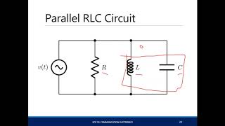
Parallel resonant circuits, comprising an inductor and capacitor configured in parallel, exhibit unique characteristics that maximize impedance at resonance, minimizing current through the circuit. Designing such circuits requires a methodical approach encompassing several key steps:
- Select the Resonant Frequency: The first step is to ascertain the desired resonant frequency (f0) necessary for the particular application.
- Choose Components: Calculate suitable values for inductance (L) and capacitance (C) based on the resonant frequency equation, ensuring that the components are commercially available.
- Calculate the Quality Factor and Bandwidth: The next step involves selecting a parallel resistance value aimed at achieving a targeted bandwidth, where the quality factor (Q) provides insight into the sharpness of resonance.
- Verify Performance: Finally, simulate the circuit to confirm that the resonance and bandwidth align with specifications, making adjustments as necessary.
This systematic design process ensures high-performance parallel resonant circuits vital for applications related to frequency selection, signal filtering, and tuning.
Youtube Videos


Audio Book
Dive deep into the subject with an immersive audiobook experience.
Step 1: Select the Resonant Frequency
Chapter 1 of 4
🔒 Unlock Audio Chapter
Sign up and enroll to access the full audio experience
Chapter Content
As with series circuits, decide on the desired resonant frequency f0f_0.
Detailed Explanation
The first step in designing a parallel resonant circuit is to determine the resonant frequency you want. This frequency is critical because it defines the point at which the circuit will operate optimally. You might choose this frequency based on the specific application of the circuit, such as filtering a certain frequency in a radio.
Examples & Analogies
Think of this step like tuning a radio. Just as you select a specific station by adjusting the dial to the frequency of that station, you need to select a specific frequency for your circuit to resonate effectively.
Step 2: Choose Components
Chapter 2 of 4
🔒 Unlock Audio Chapter
Sign up and enroll to access the full audio experience
Chapter Content
Based on the resonant frequency, calculate the L and C values using the resonant frequency equation.
Detailed Explanation
After selecting your desired resonant frequency, the next step is to determine the values of the inductor (L) and capacitor (C). You will use the formula for the resonant frequency to calculate what L and C should be to achieve that frequency. It’s important to select standard values of L and C that are widely available on the market to make procurement easier.
Examples & Analogies
Imagine you’re baking a cake and following a recipe. The resonant frequency is like the final cake flavor you want to achieve, while the L and C values are the ingredients (flour, sugar, eggs) that need to be precise to create that flavor. If you use the wrong amounts or types of ingredients, the cake won’t turn out as expected.
Step 3: Calculate the Quality Factor and Bandwidth
Chapter 3 of 4
🔒 Unlock Audio Chapter
Sign up and enroll to access the full audio experience
Chapter Content
Select the parallel resistance value to achieve the desired bandwidth. The Q factor determines the selectivity of the resonance and can be adjusted based on the circuit's requirements.
Detailed Explanation
In this step, you will calculate the quality factor (Q) and the bandwidth of your circuit. The quality factor measures how selective the circuit is at its resonant frequency—higher values mean a narrower bandwidth, which is useful if you want to focus on a specific frequency without interference. You'll also select an appropriate resistance value that helps achieve the desired bandwidth for the application.
Examples & Analogies
Think of Q factor like choosing a narrow beam of light versus a wide floodlight. If you have a narrow beam (high Q), you can focus on a specific area effectively, just like a selective circuit. A floodlight (low Q) spreads light everywhere, illuminating a broad area but losing intensity in any specific spot.
Step 4: Verify Performance
Chapter 4 of 4
🔒 Unlock Audio Chapter
Sign up and enroll to access the full audio experience
Chapter Content
After component selection, simulate the circuit and verify that the resonance and bandwidth are as desired.
Detailed Explanation
The final step involves testing your design to ensure it works as planned. You would typically use circuit simulation software to analyze how the circuit behaves at the desired frequency, checking that the impedance and bandwidth match your calculations. If the circuit doesn’t perform as expected, you may need to adjust the component values and re-test.
Examples & Analogies
This step is akin to a dress rehearsal before a performance. Just as actors practice to ensure everything works well together, ensuring that the lights, sound, and staging are perfect, you need to verify that all the components of your circuit perform well together before the ‘performance’ of the actual application.
Key Concepts
-
Parallel Resonant Circuit: A parallel configuration of L and C where impedance is maximized at resonance.
-
Resonant Frequency (f0): The point of equal reactance where circuit impedance peaks.
-
Quality Factor (Q): Indicates the circuit’s selectivity regarding its resonant frequency and bandwidth.
Examples & Applications
An example of a parallel resonant circuit can be seen in radio tuners where specific frequencies are filtered to allow certain signals through while blocking others.
A parallel LC circuit used in a high-frequency amplifier to ensure minimal current draw at unwanted frequencies.
Memory Aids
Interactive tools to help you remember key concepts
Rhymes
Maximize the Z in resonance, current's a low consequence.
Stories
Imagine a wise wizard balancing frequencies. He collects an inductor and a capacitor, and only at the right frequency, they harmonize effortlessly, showcasing their power by minimizing disturbances.
Memory Tools
Remember 'LCR' - L for inductance, C for capacitance, and R for resonance.
Acronyms
In 'LCQ', L is for inductance, C for capacitance, Q for the quality factor!
Flash Cards
Glossary
- Parallel Resonant Circuit
A circuit configuration consisting of an inductor and capacitor connected in parallel, where impedance is maximized at its resonant frequency.
- Resonant Frequency (f0)
The frequency at which the inductive reactance equals the capacitive reactance, resulting in maximum impedance.
- Quality Factor (Q)
A measure of the selectivity of the circuit, defined as the ratio of resonant frequency to bandwidth.
- Impedance
The total resistance to current flow in a circuit, typically represented in ohms.
- Bandwidth (BW)
The range of frequencies over which the circuit effectively operates, related to the quality factor.
Reference links
Supplementary resources to enhance your learning experience.