
Series Resonant Circuit
Interactive Audio Lesson
Listen to a student-teacher conversation explaining the topic in a relatable way.
Understanding Series Resonant Circuits
🔒 Unlock Audio Lesson
Sign up and enroll to listen to this audio lesson

Today, we're discussing series resonant circuits. Can anyone tell me what components are involved in such a circuit?

Are they just inductors and capacitors?
Exactly! An inductor and a capacitor are both connected in series with a signal source. What happens at resonance?

The impedance becomes really low, right?
That's correct! At resonance, the net reactance is zero, which means the total impedance is purely resistive and equals R. This leads to the maximum current flow. Can anyone remember the formula for resonant frequency?

Isn't it f₀ = 1/(2π√(LC))?
Well done! This relationship shows how inductance and capacitance determine the frequency at which the circuit resonates. Remember the acronym 'LC' for 'Legends of Circuits' to help you remember L and C. Let's move on!
Impedance and Resonant Frequency
🔒 Unlock Audio Lesson
Sign up and enroll to listen to this audio lesson

Now that we've grasped the components, let’s discuss impedance. What do we understand by impedance at resonance in our series circuit?

That it's just the resistance, right? Because reactance cancels out?
Exactly right! The impedance Z at resonance simplifies to Z = R. This leads us to current flow. Can anyone tell me how we can manipulate this circuit?
By changing L or C, we could alter the resonant frequency, and that will affect the circuit's behavior.
Correct! Adjusting either one will change the frequency at which the circuit resonates. This is crucial for many applications. Let's explore bandwidth next. Who knows the bandwidth equation?
BW equals R/L?
Exactly! Bandwidth gives us an idea of how wide a range of frequencies around f₀ the circuit will operate effectively. This is linked to our next topic, the Quality Factor, or Q.
Quality Factor and Bandwidth of Series Resonant Circuits
🔒 Unlock Audio Lesson
Sign up and enroll to listen to this audio lesson
Let’s focus now on the Quality Factor, Q. What does it measure?
It measures how selective the circuit is, right? Like, how narrow the bandwidth is?
Exactly! A higher Q means a narrower bandwidth. How is Q calculated?
Q = f₀/BW, but it can also be expressed as Q = L/RC.
Perfect! This shows how R, L, and C all work together. High Q circuits are useful for tuning applications, while lower Q is better for wideband applications. Can anyone recall how we considered these factors in practical designs?
We choose L and C to achieve the right f₀ and then select R for desired bandwidth and Q.
Exactly! Remember, balancing these parameters is key in circuit design. Let's summarize the main points we've learned.
To recap: series resonant circuits allow maximum current flow at a specific frequency determined by the values of L and C; impedance at resonance is purely resistive, and the Q factor indicates how selective the circuit is. Great job today, everyone!
Introduction & Overview
Read summaries of the section's main ideas at different levels of detail.
Quick Overview
Standard
Series resonant circuits, which consist of inductors and capacitors connected in series, resonate at specific frequencies where impedance is minimized. The section covers key concepts such as impedance at resonance, the formula for resonant frequency, the bandwidth calculation, and the implications of the quality factor, emphasizing their applications in various electronic devices.
Detailed
In a series resonant circuit, an inductor (L) and a capacitor (C) are connected in series with a signal source. At resonance, the inductive and capacitive reactances are equal and opposite, leading to minimal impedance, which allows maximum current flow through the circuit. The resonant frequency (f₀) is calculated using the formula: f₀ = 1/(2π√(LC)), highlighting the relationship between inductance and capacitance in determining the frequency at which resonance occurs. Additionally, the bandwidth (BW) is inversely related to resistance (R), calculated as BW = R/L, while the quality factor (Q) indicates resonance sharpness, expressed as Q = f₀/BW. A higher Q results in narrower bandwidth, important for applications requiring selectivity such as filters and tuners.
Youtube Videos
Audio Book
Dive deep into the subject with an immersive audiobook experience.
Overview of Series Resonant Circuits
Chapter 1 of 4
🔒 Unlock Audio Chapter
Sign up and enroll to access the full audio experience
Chapter Content
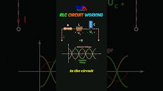
A series resonant circuit consists of an inductor and a capacitor connected in series with a signal source. At resonance, the impedance of the circuit is purely resistive, and the circuit allows maximum current to flow.
Detailed Explanation
A series resonant circuit is formed by connecting an inductor (L) and a capacitor (C) in series with a signal source. When the circuit operates at a specific frequency called the resonant frequency, the inductor and capacitor share equal but opposite reactance. This situation results in a purely resistive impedance, which means the circuit can conduct maximum current without any resistance contributing to energy loss. This feature makes series resonant circuits particularly useful for applications requiring high current flow.
Examples & Analogies
Think of a series resonant circuit like a water pipe system. When the pipe's diameter is just right (resonance), water flows through it freely without much resistance, allowing for maximum flow. But if the pipe is too narrow (off-resonance), it restricts the flow significantly.
Impedance at Resonance
Chapter 2 of 4
🔒 Unlock Audio Chapter
Sign up and enroll to access the full audio experience
Chapter Content
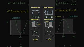
At resonance, the inductive reactance XL and capacitive reactance XC are equal and opposite, resulting in zero net reactance. The total impedance Z of the circuit is simply the resistance R of the resistor (or equivalent resistance in case of practical components). Z_resonance = R.
Detailed Explanation
In a series resonant circuit, both the inductive reactance (XL) and the capacitive reactance (XC) balance each other out at the resonant frequency. Mathematically, this means that XL = XC. Because these reactances oppose each other, the net reactance becomes zero, and the impedance of the circuit is simply equal to the resistance (R). This simplification means that the circuit is highly efficient at resonance since the total impedance is minimized to the resistance alone.
Examples & Analogies
Imagine sound waves in a musical instrument that resonate perfectly. At the right frequency, the instrument amplifies sound without distortion, similar to how reactances cancel out in a resonant circuit. Just like a well-tuned instrument allows max sound output (current), the circuit allows maximum current flow at resonance.
Resonant Frequency
Chapter 3 of 4
🔒 Unlock Audio Chapter
Sign up and enroll to access the full audio experience
Chapter Content
The resonant frequency f0 of a series LC circuit is given by:
f0 = 1 / (2π√(LC))
Where:
- L is the inductance,
- C is the capacitance.
Detailed Explanation
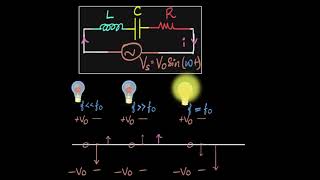
The resonant frequency (f0) is the frequency at which the series resonant circuit operates most effectively. It is calculated using the formula f0 = 1 / (2π√(LC)), where 'L' is the inductance and 'C' is the capacitance of the circuit. This relationship shows that the resonant frequency is inversely related to the square root of the product of the inductance and capacitance, meaning that higher inductance or capacitance leads to a lower resonant frequency, and vice versa.
Examples & Analogies
You can think of a swing at a playground. If you push the swing (like applying a frequency) at just the right moment (resonant frequency), it goes the highest. If you push it too early or too late, it doesn’t go very far. Similarly, in a resonant circuit, the closer the input frequency is to the resonant frequency, the more effectively the circuit can transfer energy.
Bandwidth and Quality Factor (Q)
Chapter 4 of 4
🔒 Unlock Audio Chapter
Sign up and enroll to access the full audio experience
Chapter Content
The bandwidth (BW) of the resonant circuit is the range of frequencies around f0 where the circuit can operate effectively. It is determined by the resistance R.
- BW = R / L.
The Quality Factor (Q) measures the selectivity or sharpness of the resonance:
- Q = f0 / BW = L / (CR).
A high Q factor indicates a narrow bandwidth and high selectivity.
Detailed Explanation
The bandwidth (BW) indicates the range of frequencies over which the circuit can still operate effectively. This bandwidth is influenced by the resistance (R) and can be calculated using the formula BW = R / L. The Quality Factor (Q) is an important metric in resonant circuits; it describes how selectivity or sharp the the resonant frequency is. It's defined as Q = f0 / BW, which shows how much better the circuit can isolate its resonant frequency from nearby frequencies. A high Q indicates that the resonance is sharp and the circuit is very selective, while a low Q indicates a broader range of effective frequencies.
Examples & Analogies
Consider tuning a radio. Turning the dial just a little can bring your favorite station in clearly (high Q), while a wide turn picks up all sorts of static (low Q). The bandwidth represents the fuzziness around the clear signal; a high-quality radio can pick up that clear frequency without interference from others.
Key Concepts
-
Impedance: The total opposition in a circuit, affected by both resistance and reactance.
-
Resonant Frequency: The frequency where the inductive and capacitive reactances are equal, determined by values L and C.
-
Bandwidth: The range of frequencies the circuit effectively operates in, influenced by resistance.
-
Quality Factor (Q): A measure of selectivity in resonance; higher Q indicates narrower bandwidth.
Examples & Applications
In radio tuning circuits, selecting appropriate L and C values determines the frequency at which the radio can receive signals clearly.
In amplification circuits, a series resonant circuit may be used to boost signals at a desired frequency while rejecting others.
Memory Aids
Interactive tools to help you remember key concepts
Rhymes
In series circuits, to no one's surprise, Impedance drops when reactance complies.
Stories
Imagine an orchestra where the conductor needs both strings and brass to play at the right tempo (frequency); if they do, the harmony (maximum current) is at its peak.
Memory Tools
Remember 'Q = Fat B' where each letter helps you recall: Q (Quality Factor), F (frequency), A (Amplitude), T (Time), B (Bandwidth).
Acronyms
Use 'RCA' for Remembering Circuit Analysis
Resonant frequency
Current
and Amplitude.
Flash Cards
Glossary
- Series Resonant Circuit
A circuit configuration where an inductor and capacitor are connected in series, allowing maximum current flow at resonance.
- Impedance (Z)
The total opposition a circuit presents to the flow of alternating current, consisting of both resistance and reactance.
- Resonant Frequency (f₀)
The frequency at which the inductive reactance equals the capacitive reactance, leading to maximum current flow.
- Bandwidth (BW)
The range of frequencies over which the circuit operates effectively, inversely related to resistance.
- Quality Factor (Q)
A dimensionless parameter that measures the sharpness of resonance; a high Q indicates a narrow bandwidth.
Reference links
Supplementary resources to enhance your learning experience.