
Parallel Resonant Circuit
Interactive Audio Lesson
Listen to a student-teacher conversation explaining the topic in a relatable way.
Introduction to Parallel Resonant Circuits
🔒 Unlock Audio Lesson
Sign up and enroll to listen to this audio lesson

Today, we will explore parallel resonant circuits. Can anyone tell me what happens in a parallel resonant circuit?

Isn't it where the inductor and capacitor are connected side by side?
Exactly, Student_1! The inductor and capacitor are connected in parallel, and at resonance, they cancel each other's reactance, resulting in very high impedance.

What does high impedance mean for the current in the circuit?
Good question! At resonance, current through the circuit is minimized. So we want high impedance when we need to avoid signal loss. Remember, 'High Impedance, Low Current,' or HILC for short!

Does that mean it works differently from a series resonant circuit?
Yes, it does! In a series circuit, we want to minimize impedance to allow maximum current flow. They serve different purposes in circuit design.

Are there applications where we specifically use parallel circuits?
Absolutely! They are often used in filters and tuning circuits. Let's keep these concepts in mind as we move forward.
Resonant Frequency and Bandwidth
🔒 Unlock Audio Lesson
Sign up and enroll to listen to this audio lesson

Now let's talk about how we calculate the resonant frequency. Who remembers the formula for the resonant frequency in a parallel LC circuit?
Isn't it the same as in a series circuit? Something with L and C?
Exactly, it's given by $$f_0 = \frac{1}{2\pi \sqrt{LC}}$$. We're looking for an ideal frequency for our components.
And the bandwidth? How do we calculate that?
The bandwidth is determined by the resistance in the circuit, defined by $$BW = \frac{R}{L}$$. The values of L and R play crucial roles here. A higher resistance narrows the bandwidth.
So a higher Q factor means we have a sharper resonance?
Correct! The quality factor Q measures how selective we are at our resonant frequency: $$Q = \frac{R}{\sqrt{L/C}}$$. It shows us the sharpness of the resonance.
This sounds really important for designing circuits!
Indeed! These concepts guide engineers in designing efficient circuits for specific applications.
Quality Factor and Applications
🔒 Unlock Audio Lesson
Sign up and enroll to listen to this audio lesson
Today, I want to focus on the quality factor and its implications. Why is a higher Q factor beneficial?
A higher Q means better selectivity for our desired frequency, right?
Exactly! It allows our circuit to filter out unwanted frequencies effectively. Remember, 'Quality Equals Selectivity or QES!'
What kind of applications are we talking about here?
Great question! Parallel resonant circuits are used in tuning circuits in radios and filtering applications in audio processing.
Are there specific examples where this is crucial?
Yes! For example, radio receivers rely on these circuits to select desired stations from a range of frequencies, ensuring clearer sound quality.
So, high Q means lower interference and better quality sound?
Exactly! Well done, everyone. Understanding these applications will help as we delve deeper into circuit design.
Introduction & Overview
Read summaries of the section's main ideas at different levels of detail.
Quick Overview
Standard
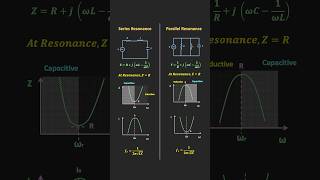
In parallel resonant circuits, the inductive and capacitive reactances counteract each other, leading to very high impedance at the resonant frequency. This section explores the characteristics, resonant frequency formula, bandwidth, and quality factor of parallel circuits, along with their significance in various applications.
Detailed
Detailed Summary
A Parallel Resonant Circuit comprises an inductor and a capacitor connected in parallel, with significant applications in signal processing and tuning. When at resonance, the impedance of the circuit becomes very high, ideally approaching infinite impedance. This high impedance results from the equal and opposite inductive and capacitive reactances, effectively limiting the current flowing through the circuit.
Key Characteristics:
1. Impedance at Resonance: The impedance is ideally infinite, reflecting the cancellation of reactances.
2. Resonant Frequency: Determined using the formula
$$f_0 = \frac{1}{2\pi \sqrt{LC}}$$
where L is inductance and C is capacitance.
3. Quality Factor (Q): Defined as
$$Q = \frac{f_0}{BW} = \frac{R}{\sqrt{L/C}}$$
A high Q factor indicates narrow bandwidth and high resonance sharpness.
4. Bandwidth: Influenced by the parallel resistance, it defines the effective operating frequency range.
Overall, parallel resonant circuits are fundamental in designing filters and oscillators, where high impedance is desirable for minimal signal losses.
Youtube Videos
Audio Book
Dive deep into the subject with an immersive audiobook experience.
Overview of Parallel Resonant Circuit
Chapter 1 of 4
🔒 Unlock Audio Chapter
Sign up and enroll to access the full audio experience
Chapter Content
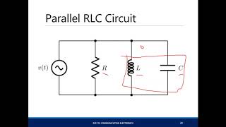
A parallel resonant circuit consists of an inductor and a capacitor connected in parallel with a signal source. At resonance, the impedance of the circuit becomes very high, and the current through the circuit is minimized.
Detailed Explanation
A parallel resonant circuit is formed when an inductor and a capacitor are connected side by side to the same two terminals of a signal source. This configuration is different from a series resonant circuit, where components are connected one after the other. At a specific frequency, known as the resonant frequency, the inductive reactance (opposition from the inductor) and capacitive reactance (opposition from the capacitor) exactly cancel each other out. As a result of this cancellation, the total impedance (resistance to current flow) of the circuit becomes very high. When the impedance is very high, it leads to a minimal current flowing through the circuit.
Examples & Analogies
Think of a parallel resonant circuit like a busy highway with a toll booth. During peak hours, traffic (representing current) is minimized because cars are stopped at the toll booth (the high impedance), causing a backup. In contrast, off-peak hours might allow cars to zoom through with little resistance.
Impedance at Resonance
Chapter 2 of 4
🔒 Unlock Audio Chapter
Sign up and enroll to access the full audio experience
Chapter Content
At resonance, the inductive reactance and capacitive reactance are equal and opposite, resulting in infinite impedance in the ideal case. In a practical scenario, the impedance is limited by the resistance of the inductor and any losses in the circuit.
Detailed Explanation
In a perfect scenario, when the parallel resonant circuit reaches its resonant frequency, the effects of the inductor and capacitor perfectly oppose each other. Since reactances cancel out, the circuit theoretically achieves infinite impedance. However, in real-world applications, all components have some resistance. Therefore, when you measure impedance, you'll find it is very high but not truly infinite due to these resistive losses. This high impedance at resonance means that the circuit does not draw much current, which is useful for many applications like filtering.
Examples & Analogies
Imagine a perfectly balanced seesaw; at the center, it stays perfectly horizontal and does not move (infinite stability). In practical terms, though, if there’s a bit of weight on one side (the resistance), the seesaw tilts slightly, but is still very stable. Similarly, in a real circuit, loads slightly affect the balance, but the high impedance remains.
Resonant Frequency of Parallel Circuit
Chapter 3 of 4
🔒 Unlock Audio Chapter
Sign up and enroll to access the full audio experience
Chapter Content
The resonant frequency f0 of a parallel LC circuit is the same as in the series circuit: f0 = 1/(2π√(LC)).
Detailed Explanation
The resonant frequency is the frequency at which the circuit naturally oscillates when not driven by an external source. For both series and parallel resonant circuits, the formula for finding this frequency is identical. It depends on the inductance (L) of the inductor and the capacitance (C) of the capacitor. The formula f0 = 1/(2π√(LC)) shows that resonant frequency decreases with increasing inductance or capacitance.
Examples & Analogies
Think of resonant frequency as the natural frequency at which a swing or a playground seesaw moves when pushed gently. The longer the swing or the heavier the seesaw (more inductance or capacitance), the slower its natural movement (lower resonant frequency).
Bandwidth and Quality Factor (Q)
Chapter 4 of 4
🔒 Unlock Audio Chapter
Sign up and enroll to access the full audio experience
Chapter Content
The bandwidth is determined by the parallel resistance R, and the Q factor is defined as: Q = f0/BW = R/√(L/C). A high Q factor in parallel resonance indicates a narrow bandwidth and high resonance sharpness.
Detailed Explanation
In the context of a parallel resonant circuit, bandwidth refers to the range of frequencies over which the circuit can adequately function around its resonant frequency. It is influenced by the resistance present in the circuit. The Quality Factor (Q) measures the sharpness of the resonance peak. A higher Q indicates that the circuit is very selective to its resonant frequency (narrow bandwidth). Conversely, a lower Q factor would mean that the circuit can handle a wider range of frequencies but is less selective.
Examples & Analogies
Imagine a concert hall. If the acoustics are tuned perfectly (high Q), only specific frequencies of music sound great, while other tones are drowned out (narrow bandwidth). If the hall is poorly designed (low Q), you would hear a mix of sounds, making it harder to enjoy a particular song.
Key Concepts
-
Impedance: At resonance in parallel circuits, impedance can approach infinity, minimizing current.
-
Resonant Frequency: Given by the formula $$f_0 = \frac{1}{2\pi \sqrt{LC}}$$, the same as in series circuits.
-
Quality Factor (Q): A high Q indicates narrow bandwidth and increased selectivity in filtering applications.
-
Bandwidth: Defined by the resistance in the circuit, determining the effective range of operation.
Examples & Applications
An example of a parallel resonant circuit is its use in radio tuning, filtering out undesired stations while allowing the desired frequency to pass through.
In audio applications, parallel resonant circuits help eliminate noise and improve sound quality by focusing on specific frequency bands.
Memory Aids
Interactive tools to help you remember key concepts
Rhymes
In a parallel loop, impedance goes high, current stays low, oh me, oh my!
Stories
Imagine a busy town where the inductor and capacitor are busy negotiating. At the peak of their discussions, they agree to cancel each other out, leaving the signal riding in high style—barely a ripple in the current flowing by.
Memory Tools
For series, 'Low Impact Is High' while for parallel, 'High Impact, Low Current' - remember LICH for series and HILC for parallel!
Acronyms
QES - Quality Equals Selectivity to easily remember the role of Quality Factor.
Flash Cards
Glossary
- Resonance
A condition in a circuit where the inductive and capacitive reactances are equal and opposite.
- Impedance
The total opposition a circuit offers to current flow, influenced by resistance, inductance, and capacitance.
- Quality Factor (Q)
A dimensionless parameter that describes the selectivity or sharpness of resonance in a circuit.
- Bandwidth (BW)
The range of frequencies over which the circuit operates effectively.
- Inductor
A passive component that stores energy in a magnetic field when electrical current passes through it.
- Capacitor
A passive component that stores electricity in an electric field and releases it when needed.
Reference links
Supplementary resources to enhance your learning experience.