
Impedance at Resonance - 3.2.2.1
Interactive Audio Lesson
Listen to a student-teacher conversation explaining the topic in a relatable way.
Understanding Impedance in Parallel Resonant Circuits
🔒 Unlock Audio Lesson
Sign up and enroll to listen to this audio lesson

Today we are going to delve into the impedance characteristics of parallel resonant circuits. Can anyone remind me of what happens with the inductive and capacitive reactance at resonance?

They balance each other out, right? XL equals XC.
Exactly! When XL equals XC, the net reactance is zero. So, what does that mean for the impedance of the circuit?

The impedance would be very high, approaching infinity, because there's no current flowing through the circuit.
Great point! In an ideal case, yes. This leads us to a crucial application of parallel resonant circuits in tuning and filtering. Let’s remember 'High Impedance at resonance' for our notes.
Practical Considerations in Impedance
🔒 Unlock Audio Lesson
Sign up and enroll to listen to this audio lesson

Now that we understand the theoretical implications of high impedance, what do you think happens in real circuits where we have resistive losses?

The impedance would not actually be infinite, would it? It would be limited by the resistances present.
Correct! Practical circuits have resistive components that limit the impedance. This means we have to design our circuits considering those losses to ensure effective performance. Can anyone think of an application where this is particularly important?

In antenna matching systems, you want to maximize power transfer, but too high impedance at resonance might not be beneficial.
Exactly! Antenna designers need to take these impedance characteristics into account to achieve efficient communication. Let's summarize: while parallel resonance offers infinite impedance theoretically, real-world factors are always at play!
Resonant Frequency and Its Role
🔒 Unlock Audio Lesson
Sign up and enroll to listen to this audio lesson
Next, how do we determine the resonant frequency in a parallel resonant circuit?
Using the formula f0 = 1/(2π√(LC)).
Absolutely! And at this frequency, what trend do you observe regarding our impedance?
It reaches that high value, which is ideal for minimizing current flow but allows very selective frequency tuning.
Exactly! This highlights the utility of the formula and the concept of impedance in tuning applications. Remember, 'Resonant Frequency: High Impedance Ideal for Selective Tuning!'
Introduction & Overview
Read summaries of the section's main ideas at different levels of detail.
Quick Overview
Standard
The section elaborates on the nature of impedance in a parallel resonant circuit, explaining that at resonance, the reactive components balance out, resulting in high impedance. Practical implications are also touched upon, including the limitations posed by real components.
Detailed
Impedance at Resonance
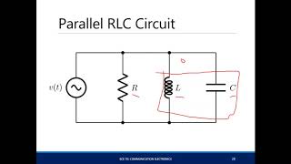
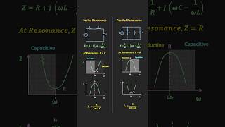
In parallel resonant circuits, the impedance behavior is significantly different from that of series circuits. At resonance, the inductive reactance (XL) and capacitive reactance (XC) are equal and cancel each other out, leading to a condition where the total impedance theoretically approaches infinity in an ideal scenario. In practice, however, losses due to resistance in the inductor and other circuit resistances limit this impedance. This section is vital as understanding the impedance characteristics at resonance is crucial for applications in filtering, tuning, and frequency selection where minimal current flow is desired, while still allowing signal passage at specific resonant frequencies.
Youtube Videos
Audio Book
Dive deep into the subject with an immersive audiobook experience.
Understanding Impedance at Resonance in Parallel Circuits
Chapter 1 of 2
🔒 Unlock Audio Chapter
Sign up and enroll to access the full audio experience
Chapter Content
At resonance, the inductive reactance and capacitive reactance are equal and opposite, resulting in infinite impedance in the ideal case. In a practical scenario, the impedance is limited by the resistance of the inductor and any losses in the circuit.
Z_{resonance} = ∞ \quad \text{(ideal)}
Detailed Explanation
In a parallel resonant circuit, at the point of resonance, the reactance caused by the inductor (which resists changes in current) and the reactance caused by the capacitor (which resists changes in voltage) balance each other out. This means that their effects cancel each other, leading to very high impedance across the circuit. While in theory, this leads to infinite impedance because of the cancellation, real circuits have resistive elements that prevent this from happening entirely, resulting instead in very high but finite impedance.
Examples & Analogies
Imagine a seesaw where two children of equal weight sit at opposite ends; the seesaw becomes perfectly balanced and does not move. In the same way, when the reactances of the inductor and capacitor are equal, the circuit becomes balanced and presents very high impedance, minimizing current flow just like the balanced seesaw remains still.
Comparing Ideal and Practical Scenarios
Chapter 2 of 2
🔒 Unlock Audio Chapter
Sign up and enroll to access the full audio experience
Chapter Content
In a practical scenario, the impedance is limited by the resistance of the inductor and any losses in the circuit.
Detailed Explanation
In reality, every inductor and capacitor has some inherent resistance and can introduce losses due to heat and other factors. This means that, instead of achieving infinite impedance at resonance, the actual impedance will be very high but limited by these resistive components. Such losses in real circuits affect the efficiency of energy transfer and impact how sharply the circuit can resonate.
Examples & Analogies
Think of a perfectly smooth, frictionless bicycle on a perfectly flat surface moving forever without slowing down—this is the 'ideal' scenario. In contrast, if that same bicycle is on a rough surface with bumps and friction, it slows down over time; this represents a practical scenario. Just as the rough surface limits the bicycle's distance, the resistance in our circuit limits how high the impedance can get.
Key Concepts
-
Impedance at Resonance: The impedance in parallel resonant circuits approaches infinity theoretically but is limited by practical resistances.
-
Resonant Frequency (f0): The frequency at which inductive and capacitive reactance balance, determining the circuit's impedance behavior.
-
Real-world Implications: The ideal conditions of impedance don’t always hold due to real-world losses and resistance.
Examples & Applications
In a practical parallel resonant circuit used in radio frequency applications, the impedance at resonance helps to filter unwanted signals while allowing the desired frequency to pass through with maximum efficiency.
A parallel resonant circuit used in an antenna system can achieve high selectivity, ensuring only the intended frequency range is transmitted, keeping unwanted interference to a minimum.
Memory Aids
Interactive tools to help you remember key concepts
Rhymes
When L and C come close in line, the impedance does reach high incline.
Stories
Imagine a race where two friends, Inductive and Capacitive, always cancelled each other out. One day they balanced perfectly, and the result was a crowded calm—high impedance where no current flowed!
Memory Tools
Remember L for low frequency and C for cancel, together they maximize at resonance.
Acronyms
R.I.C (Resonance Impedance is Cancelled) to remember that at resonance, impedance ideally cancels out.
Flash Cards
Glossary
- Impedance
The total opposition that a circuit offers to the flow of alternating current, comprising both resistance and reactance.
- Resonant Frequency (f0)
The frequency at which the inductive and capacitive reactances are equal, resulting in a specific behavior of the circuit's impedance.
- Inductive Reactance (XL)
The opposition to AC current flow caused by inductance, calculated as XL = 2πfL.
- Capacitive Reactance (XC)
The opposition to AC current flow caused by capacitance, calculated as XC = 1/(2πfC).
Reference links
Supplementary resources to enhance your learning experience.