
Design and Analysis of Resonant Circuits
Interactive Audio Lesson
Listen to a student-teacher conversation explaining the topic in a relatable way.
Introduction to Resonant Circuits
🔒 Unlock Audio Lesson
Sign up and enroll to listen to this audio lesson

Welcome everyone! Today, we are going to dive into resonant circuits. Can anyone tell me what a resonant circuit is?

Isn't it like a circuit with inductors and capacitors?
Exactly! They are often called LC circuits. At a specific frequency, the inductive and capacitive reactances cancel each other out. This leads us to a very interesting phenomenon where the impedance is minimized in a series configuration. Can anyone name a few applications of these circuits?

They are used in filters, right?
That's correct! Filters, oscillators, and even signal amplification in radio receivers. Remember, we can use the mnemonic 'FOS' to remember these applications: Filters, Oscillators, Signal amplification.

What does it mean when we say the impedance is minimized?
Good question! At resonance in a series resonant circuit, the only impedance we have is the resistance of the circuit, which maximizes current flow. Let's hold on to that thought.

So, if series circuits have low impedance, what about parallel ones?
In parallel circuits, at resonance, the impedance is actually very high, which means less current flows. To summarize, resonant circuits are crucial for efficient energy transfer in many electronic devices.
Types of Resonant Circuits
🔒 Unlock Audio Lesson
Sign up and enroll to listen to this audio lesson

Let's move on to the types of resonant circuits. Can anyone tell me the two types we studied?
There are series and parallel resonant circuits!
Right! In a series resonant circuit, the components are connected one after the other. At resonance, the total impedance becomes purely resistive. Now, how about the parallel circuit?
In a parallel resonant circuit, the components are connected side by side, and the impedance becomes very high, right?
Exactly! High impedance in parallel means minimal current. Here’s a mnemonic: 'SP' for Series = Pure resistive, Parallel = High impedance.
What’s the resonant frequency in both cases?
Great question! For both types, it's given by the same formula: `f₀ = 1/(2π√(LC))`. It helps us understand how to design resonant circuits.
And how is bandwidth related to these circuits?
Bandwidth is crucial as it indicates the frequency range over which the circuit operates effectively, determined by the circuit's resistance. Let’s remember: High Q leads to narrow bandwidth in both configurations.
Design of Resonant Circuits
🔒 Unlock Audio Lesson
Sign up and enroll to listen to this audio lesson
Now let's talk about how we actually design these resonant circuits. What’s the first step in designing a series resonant circuit?
Choosing the resonant frequency?
Correct! Once we choose f₀, we can calculate L and C values using the resonance formula. What’s next?
Calculating the bandwidth and quality factor?
Spot on! It ensures our circuit meets application requirements. Remember the acronym BQ for Bandwidth-Quality factor combo!
And how do we verify performance?
Performance verification involves simulating the circuit. Adjust values if needed. It’s essential for ensuring functionality.
Are the steps in parallel design the same?
Absolutely! Just similar with slight modifications depending on parallel resistance. Keep the process in mind, it helps in practical applications like filters and oscillators.
Practical Applications of Resonant Circuits
🔒 Unlock Audio Lesson
Sign up and enroll to listen to this audio lesson
Let’s now look into the practical applications. Who can name a few places where we use resonant circuits?
In filters for signals?
Exactly! They form the backbone of many types of filters. Other examples?
In oscillators to generate waveforms?
Right again! Oscillators utilize feedback from LC circuits. Remember the term FLO for Filters, Local oscillation!
And impedance matching too, right?
That's correct! Impedance matching ensures maximum power transfer in communication systems. Ultimately, understanding these applications helps you design more effective circuits.
Introduction & Overview
Read summaries of the section's main ideas at different levels of detail.
Quick Overview
Standard
Resonant circuits, also known as LC circuits, are analyzed for their fundamental roles in RF and HF applications. The section covers series and parallel resonant circuits, detailing their design parameters such as resonant frequency, impedance, bandwidth, and quality factor, as well as their practical applications in filtering, oscillation, tuning, and impedance matching.
Detailed
Design and Analysis of Resonant Circuits
Resonant circuits, or LC circuits, are essential in radio frequency (RF) and high frequency (HF) applications, designed to operate at specific resonant frequencies where inductive and capacitative reactances cancel each other. This section presents both series and parallel resonant circuits with key concepts such as:
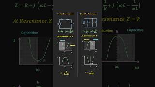
- Impedance at Resonance:
- In a series resonant circuit, impedance is minimized, allowing maximum current flow, while in a parallel circuit, impedance is maximized, minimizing current flow.
- Resonant Frequency:
-
The formula for resonant frequency (f₀) is given as
f₀ = 1/(2π√(LC)), applicable to both series and parallel circuits. - Bandwidth and Quality Factor (Q):
- Bandwidth determines the effective frequency range around f₀, related to resistance in the circuit, while the Quality Factor measures resonance sharpness and selectivity.
- Design Principles:
- Steps include selecting desired frequencies and components, calculating bandwidth and quality factor, and verifying performance through simulation.
- Practical Applications:
- Resonant circuits are employed in filters, oscillators, tuning circuits, and impedance matching networks, showcasing their versatility in communication technologies.
Youtube Videos
Audio Book
Dive deep into the subject with an immersive audiobook experience.
Introduction to Resonant Circuits
Chapter 1 of 7
🔒 Unlock Audio Chapter
Sign up and enroll to access the full audio experience
Chapter Content
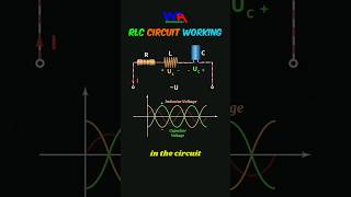
Resonant circuits, also known as LC circuits, are fundamental in RF and HF circuit design. These circuits are designed to resonate at a particular frequency, where the inductive reactance and capacitive reactance cancel each other out. At resonance, the impedance of the circuit is minimized in a series configuration or maximized in a parallel configuration, allowing for maximum energy transfer. Resonant circuits are widely used in applications such as:
● Frequency selection: Used in filters, oscillators, and tuning circuits.
● Signal amplification: In radio and TV receivers, amplifying signals at specific frequencies.
● Impedance matching: Ensuring efficient energy transfer in antenna and communication systems. This chapter covers the design, analysis, and practical applications of resonant circuits.
Detailed Explanation
Resonant circuits, often referred to as LC circuits, consist of an inductor (L) and a capacitor (C) connected in such a way that they resonate at a specific frequency. At this resonant frequency, the circuit's inductive effects balance out the capacitive effects, which means the circuit can transfer energy most efficiently. This characteristic is crucial in radio frequency (RF) and high frequency (HF) applications where selecting specific frequencies is necessary, such as in filters or oscillators.
Examples & Analogies
Think of a resonant circuit like a swing on a playground. When you push the swing at just the right moment (the swing's resonant frequency), it goes higher and higher. If you push at the wrong times, the swing either doesn’t go very high or may even go backward. Just like in circuits, where energy is most efficiently transferred at the right frequency.
Types of Resonant Circuits
Chapter 2 of 7
🔒 Unlock Audio Chapter
Sign up and enroll to access the full audio experience
Chapter Content
There are two primary types of resonant circuits: Series Resonant Circuits and Parallel Resonant Circuits. Both configurations involve inductors (L) and capacitors (C) and exhibit unique behaviors at resonance.
Detailed Explanation
Resonant circuits are generally categorized into two types: series resonant circuits and parallel resonant circuits. In a series resonant circuit, the inductor and capacitor are connected in line with each other, while in a parallel resonant circuit, they're wired side by side. Each configuration has distinct characteristics and behaviors at resonance, which impacts how they function in practical applications.
Examples & Analogies
Imagine a tuning fork for series circuits; when struck, it vibrates at a specific frequency. Now, think of a group of people singing in harmony at that frequency; the series circuit is like the tuning fork leading the individuals in a line, while the parallel circuit is like a choir where everyone sings separately but harmonizes together. Each type supports unique roles in creating the desired sound (or in our case, frequency response).
Series Resonant Circuit
Chapter 3 of 7
🔒 Unlock Audio Chapter
Sign up and enroll to access the full audio experience
Chapter Content
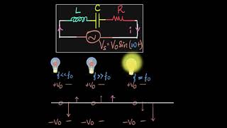
A series resonant circuit consists of an inductor and a capacitor connected in series with a signal source. At resonance, the impedance of the circuit is purely resistive, and the circuit allows maximum current to flow.
● Impedance at Resonance:
At resonance, the inductive reactance XL and capacitive reactance XC are equal and opposite, resulting in zero net reactance. The total impedance Z of the circuit is simply the resistance R of the resistor (or equivalent resistance in case of practical components).
Z_resonance = R
● Resonant Frequency:
The resonant frequency f0 of a series LC circuit is given by:
f0 = 1/(2π√(LC))
Where:
○ L is the inductance,
○ C is the capacitance.
● Bandwidth and Quality Factor (Q):
○ The bandwidth (BW) of the resonant circuit is the range of frequencies around f0 where the circuit can operate effectively. It is determined by the resistance R.
BW = R/L
○ The Quality Factor (Q) measures the selectivity or sharpness of the resonance:
Q = f0/BW = (L/CR)
A high Q factor indicates a narrow bandwidth and high selectivity.
Detailed Explanation
In a series resonant circuit, the arrangement of the inductor and capacitor allows maximum current to flow when the circuit operates at its resonant frequency. This happens because the inductive reactance and capacitive reactance cancel each other out. The circuit's ability to resonate at a particular frequency is determined by the values of inductance and capacitance, which can be calculated with the provided formula. The circuit's bandwidth and quality factor further describe its performance and selectivity at that frequency.
Examples & Analogies
Consider a well-tuned guitar string. When you strike it at the right frequency, it resonates beautifully. Similarly, a series resonant circuit ‘sings’ at a specific frequency where it allows the maximum flow of electricity. If you try playing it (or operating the circuit) with a different frequency, it just won’t produce the same clear sound.
Parallel Resonant Circuit
Chapter 4 of 7
🔒 Unlock Audio Chapter
Sign up and enroll to access the full audio experience
Chapter Content
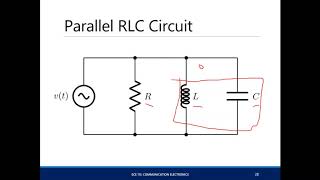
A parallel resonant circuit consists of an inductor and a capacitor connected in parallel with a signal source. At resonance, the impedance of the circuit becomes very high, and the current through the circuit is minimized.
● Impedance at Resonance:
At resonance, the inductive reactance and capacitive reactance are equal and opposite, resulting in infinite impedance in the ideal case. In a practical scenario, the impedance is limited by the resistance of the inductor and any losses in the circuit.
Z_resonance = ∞ (ideal)
● Resonant Frequency:
The resonant frequency f0 of a parallel LC circuit is the same as in the series circuit:
f0 = 1/(2π√(LC))
● Bandwidth and Quality Factor (Q):
○ The bandwidth is determined by the parallel resistance R, and the Q factor is defined as:
Q = f0/BW = R/(√(L/C))
A high Q factor in parallel resonance indicates a narrow bandwidth and high resonance sharpness.
Detailed Explanation
In parallel resonant circuits, the inductor and capacitor configuration serves to minimize current while increasing impedance at resonance. Just like in series configurations, the resonant frequency can be calculated the same way; however, the behavior of the circuit differs significantly, especially in terms of how energy is stored and dissipated. The resonant quality and bandwidth depend on the resistance and the arrangement of the circuit components.
Examples & Analogies
Picture a seesaw; when balanced at the center (resonance), it is stable with little movement (the circuit's minimal current). If you put more weight on one side (an unbalanced frequency), it tips and swings wildly. This imbalance represents the circuit's inability to stay in tune, just like currents aren't 'flowing' correctly when they aren't at resonance in parallel circuits.
Design of Resonant Circuits
Chapter 5 of 7
🔒 Unlock Audio Chapter
Sign up and enroll to access the full audio experience
Chapter Content
Designing resonant circuits involves selecting the right combination of inductance and capacitance to achieve the desired resonant frequency and quality factor. The steps in designing a resonant circuit are as follows:
3.3.1 Series Resonant Circuit Design
● Step 1: Select the Resonant Frequency
Decide the desired resonant frequency f0 for your application (e.g., a specific radio frequency, or a target frequency for a filter).
● Step 2: Choose Components
Based on the desired resonant frequency, calculate the values of L and C using the resonant frequency equation:
f0 = 1/(2π√(LC))
Select suitable values of L and C that are commercially available.
● Step 3: Calculate the Bandwidth and Quality Factor
Using the Q factor equation, select an appropriate resistor value to ensure that the bandwidth is suitable for your application. A higher Q results in a narrower bandwidth, which is useful in applications such as selective filters.
● Step 4: Verify Performance
After selecting components, simulate the circuit to verify its performance and adjust component values if necessary.
3.3.2 Parallel Resonant Circuit Design
● Step 1: Select the Resonant Frequency
As with series circuits, decide on the desired resonant frequency f0.
● Step 2: Choose Components
Based on the resonant frequency, calculate the L and C values using the resonant frequency equation.
● Step 3: Calculate the Quality Factor and Bandwidth
Select the parallel resistance value to achieve the desired bandwidth. The Q factor determines the selectivity of the resonance and can be adjusted based on the circuit's requirements.
● Step 4: Verify Performance
After component selection, simulate the circuit and verify that the resonance and bandwidth are as desired.
Detailed Explanation
Designing a resonant circuit is an organized process that involves selecting the appropriate inductors and capacitors to achieve desired outcomes. Each step must be followed carefully to ensure that the circuit resonates at the intended frequency and has the required performance characteristics. This involves calculations of component values and using simulations to fine-tune the circuit before final implementation.
Examples & Analogies
Consider designing a roller coaster; you’d want to pick the perfect angles and heights so that it speeds through the twists just right (like frequency) and doesn't topple over (like ensuring the circuit remains stable). Just as the design involves careful consideration of safety and thrill factors, designing a resonant circuit requires meticulous planning to ensure it operates efficiently at its resonant frequency.
Practical Applications of Resonant Circuits
Chapter 6 of 7
🔒 Unlock Audio Chapter
Sign up and enroll to access the full audio experience
Chapter Content
Resonant circuits are used in a variety of RF and HF applications, including:
● Filters: Resonant circuits are the foundation of many types of filters (low-pass, high-pass, band-pass, and band-stop). These filters use resonant components to selectively pass or block certain frequencies.
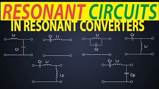
● Oscillators: Resonant circuits are used in oscillators to generate continuous waveforms at specific frequencies. The feedback from a resonant LC circuit is used to sustain oscillations.
● Tuning Circuits: Used in radios and other communication devices to select a specific frequency from a range of possible signals. The resonant circuit is tuned to resonate at the frequency of interest.
● Impedance Matching: Resonant circuits are often used in impedance matching networks to ensure maximum power transfer between different stages of a circuit, such as between antennas and transmission lines.
Detailed Explanation
Resonant circuits play a crucial role in technology we encounter every day. Their ability to filter, generate, and match frequencies makes them vital in devices like radios, televisions, and communication systems. Each application takes advantage of specific resonant characteristics to enhance performance and efficiency in handling signals.
Examples & Analogies
Think about tuning a radio to find your favorite station. The resonant circuit is like your ear tuning in to that exact pitch of your favorite song while ignoring the rest. It amplifies only the 'right' frequencies while blocking everything else, allowing us to enjoy clear sound without interference.
Summary of Key Concepts
Chapter 7 of 7
🔒 Unlock Audio Chapter
Sign up and enroll to access the full audio experience
Chapter Content
● Resonant Circuits are essential in RF and HF applications, offering efficient signal selection, filtering, and amplification.
● Series Resonant Circuits minimize impedance at resonance and are used in applications requiring maximum current flow.
● Parallel Resonant Circuits maximize impedance at resonance and are used in applications requiring high impedance and minimal current flow.
● Design of Resonant Circuits involves selecting the right components (inductance and capacitance) to achieve the desired resonant frequency and performance.
● Applications of resonant circuits include filters, oscillators, impedance matching, and tuning circuits.
Detailed Explanation
The key concepts around resonant circuits highlight their pivotal role in modern electronics. Understanding how these circuits function, the difference between series and parallel configurations, and their applications allows engineers to design systems that efficiently handle frequencies, ensuring quality performance across devices.
Examples & Analogies
Imagine making a smoothie. You need just the right mix of fruits (inductance and capacitance) to create a delicious blend (perfect resonance) - too much of one fruit or the wrong combination leads to a not-so-great drink! Similarly, a well-designed resonant circuit has to mix its components just right to function optimally.
Key Concepts
-
Resonant Circuits: LC circuits designed to resonate at specific frequencies.
-
Impedance: Total opposition to current flow affected by circuit components.
-
Resonant Frequency: Frequency at which reactances cancel out.
-
Quality Factor (Q): Measures the sharpness of the resonance.
-
Bandwidth (BW): Range of frequencies effective around the resonant frequency.
Examples & Applications
A series resonant circuit in a radio tuner allows users to select specific stations by filtering desired frequencies.
A parallel resonant circuit in a television receiver minimizes interference, enhancing the clarity of the signal.
Memory Aids
Interactive tools to help you remember key concepts
Rhymes
In circuits where L and C go, at resonance, energy flows high, you know!
Stories
Imagine a concert, where two singers (L and C) work in harmony. When they hit the right note (resonance), the sound fills the space (maximized power transfer) perfectly, creating energy that travels far.
Memory Tools
Remember 'RISE': Resonant circuits Increment Selective Energy.
Acronyms
FOS
Filters
Oscillators
Signal amplification - key applications for resonant circuits.
Flash Cards
Glossary
- Inductive Reactance
The opposition to current flow by an inductor due to its inductance, measured in ohms.
- Capacitive Reactance
The opposition to current flow by a capacitor due to its capacitance, also measured in ohms.
- Impedance (Z)
The total opposition a circuit presents to the flow of alternating current, comprising both resistance and reactance.
- Resonant Frequency (f₀)
The frequency at which the impedance of a circuit is minimized in series circuits or maximized in parallel circuits.
- Quality Factor (Q)
A dimensionless parameter that measures the selectivity of a resonant circuit; higher values indicate sharper resonance.
- Bandwidth (BW)
The frequency range over which a circuit operates effectively around its resonant frequency.
Reference links
Supplementary resources to enhance your learning experience.