
Step 1: Select the Resonant Frequency - 3.3.1.1
Interactive Audio Lesson
Listen to a student-teacher conversation explaining the topic in a relatable way.
Understanding Resonant Frequency
🔒 Unlock Audio Lesson
Sign up and enroll to listen to this audio lesson

Today, we'll start by discussing resonant frequency. Why do we need to select a specific resonant frequency for a circuit design?

Isn't it because it affects how well the circuit works?
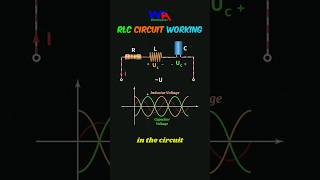
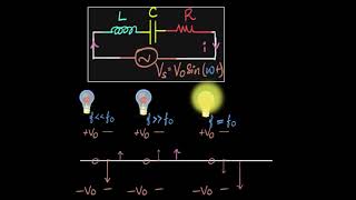
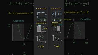
Exactly! The resonant frequency is where we achieve maximum current flow in our series resonant circuits. It’s crucial for applications like filters and amplifiers.

How do we calculate it?
Good question! We use the formula: \( f₀ = \frac{1}{2\pi\sqrt{LC}} \). Remember, L is inductance and C is capacitance; they determine our resonant frequency.
The Role of Components in Resonance
🔒 Unlock Audio Lesson
Sign up and enroll to listen to this audio lesson

Now, let’s explore how inductance and capacitance affect the resonant frequency. If we want a higher frequency, what should we do with L and C?

We would want to decrease L or C, right?
Precisely! Decreasing inductance or capacitance raises the resonant frequency. It's key to remember how these values interact.

What if we changed both values instead of one?
Great thought! If you adjust both, you'll need to recalculate f₀, keeping the balance so it meets your design goals.
Application of Resonant Frequency
🔒 Unlock Audio Lesson
Sign up and enroll to listen to this audio lesson
Let’s discuss where resonant frequency is used in real-life applications. Why is it critical in filters and oscillators?
Because it helps select specific frequencies to pass or block signals.
Exactly! In filters, we want to isolate certain frequencies, and in oscillators, we need to generate those frequencies continuously.
And it all starts with how we choose that resonant frequency.
Correct! The initial selection sets the stage for our entire circuit design.
Introduction & Overview
Read summaries of the section's main ideas at different levels of detail.
Quick Overview
Standard
In this section, students learn about the importance of selecting the resonant frequency for a series resonant circuit design. It emphasizes the role of resonant frequency in applications like filtering and amplification, setting the foundation for further steps in the design process.
Detailed
Overview
Selecting the resonant frequency is the crucial first step in the design of a series resonant circuit. The resonant frequency, denoted as f₀, plays a significant role in defining how the circuit behaves in various applications, such as filters and oscillators. By understanding the relationship between frequency, inductance (L), and capacitance (C), students can determine suitable component values to meet their design specifications.
Key Points
- Importance of f₀: Resonant frequency is the point where the circuit offers maximum current flow in series configurations, making it essential for efficient circuit functionality.
- Calculation Formula: The resonant frequency can be calculated using the formula:
$$f₀ = \frac{1}{2\pi\sqrt{LC}}$$
where L is the inductance, and C is the capacitance. This formula highlights the interdependent relationship between these parameters and the resonant frequency.
By properly selecting the resonant frequency, designers can tailor their circuits for efficient performance in their intended applications.
Youtube Videos
Audio Book
Dive deep into the subject with an immersive audiobook experience.
Deciding the Desired Resonant Frequency
Chapter 1 of 1
🔒 Unlock Audio Chapter
Sign up and enroll to access the full audio experience
Chapter Content
Decide the desired resonant frequency f0 for your application (e.g., a specific radio frequency, or a target frequency for a filter).
Detailed Explanation
The first step in designing a series resonant circuit involves deciding on the resonant frequency, denoted as f0. This frequency is crucial because it determines how the circuit will behave and which applications it will serve. The designer needs to consider various factors, such as the specific radio frequency they wish to target or a frequency required for filtering signals.
Examples & Analogies
Think of it like tuning a guitar. Just as a musician selects a specific pitch to tune their strings, an engineer selects a specific frequency for the circuit. If the guitar is tuned to the correct pitch, the music sounds harmonious; similarly, when the resonant frequency is correctly chosen, the circuit operates efficiently and delivers optimal performance.
Key Concepts
-
Resonant Frequency: The specific frequency at which a resonant circuit is designed to operate most effectively.
-
Inductance and Capacitance: The two key parameters that determine the resonant frequency of a circuit.
Examples & Applications
In a radio tuner, selecting a resonant frequency allows the tuner to isolate and amplify a particular radio signal.
In a filter circuit, the resonant frequency can be set to allow specific frequency ranges to pass while blocking undesired frequencies.
Memory Aids
Interactive tools to help you remember key concepts
Rhymes
In circuits where current must flow, resonant frequency we need to know!
Stories
Imagine a radio that can only play one song at a time. By setting its resonant frequency, it knows exactly which song to play!
Memory Tools
Remember L and C: Larger C means Lower f₀; Lower C means Higher f₀.
Acronyms
Try LCR
for Inductance
for Capacitance
and R for Resonance.
Flash Cards
Glossary
- Resonant Frequency
The frequency at which a circuit's inductive reactance and capacitive reactance are equal, resulting in maximum current flow in series circuits.
- Inductance (L)
The property of an inductor that opposes changes in current, measured in Henries (H).
- Capacitance (C)
The ability of a capacitor to store charge, measured in Farads (F).
Reference links
Supplementary resources to enhance your learning experience.