
Resonant Frequency - 3.2.2.2
Interactive Audio Lesson
Listen to a student-teacher conversation explaining the topic in a relatable way.
Understanding Resonant Frequency in Parallel Circuits
🔒 Unlock Audio Lesson
Sign up and enroll to listen to this audio lesson

Today, we’re going to discuss resonant frequency in parallel resonant circuits. Can anyone tell me what happens at resonant frequency?

I think the current is minimized?
Correct! At resonance, the impedance is very high, and ideally, it can be considered infinite. This minimizes the current flowing through the circuit. Great job!

What does that mean for energy transfer?
That's an important point! High impedance means that energy is not dissipated through current flow at this frequency, maximizing energy storage in the circuit elements, L and C.

How do we find the actual frequency?
Good question! The resonant frequency can be calculated with the formula: f₀ = 1/(2π√(LC)). Remember this; you might find it helpful to think of it as controlling your circuit's 'speed' by tuning the values of L and C!
Importance of Quality Factor (Q)
🔒 Unlock Audio Lesson
Sign up and enroll to listen to this audio lesson

Now that we've covered resonant frequency, let’s discuss the Quality Factor, or Q. Who remembers what Q is?

Isn’t it about how selective the circuit is around the resonant frequency?
Exactly! Q is calculated as Q = R/√(L/C). A higher Q means better selectivity and a narrower bandwidth. Can anyone think of an application where this would be useful?
In tuning circuits, right? Like in radios?
Absolutely! High Q within tuning allows for precise signal acquisition, enabling clear sound without interference.
Practical Examples of Resonant Frequency
🔒 Unlock Audio Lesson
Sign up and enroll to listen to this audio lesson
Let’s discuss some practical applications of parallel resonant circuits. Can someone give an example?
Filters in audio equipment?
Yes, filters! They use resonant circuits to allow only certain frequencies to pass. What happens if the Q is too high in such cases?
It might block too many frequencies and not allow enough through?
Yes! That’s a crucial concept. Tuning Q helps us ensure the filter is effective but not overly selective. This balance is key in designs!
Introduction & Overview
Read summaries of the section's main ideas at different levels of detail.
Quick Overview
Standard
Resonant frequency is a critical property in parallel resonant circuits, where the impedance becomes very high at resonance, effectively minimizing current flow. This concept is crucial for understanding energy transfer, bandwidth, and the quality factor (Q) for various applications in RF and HF circuits.
Detailed
Detailed Summary of Resonant Frequency
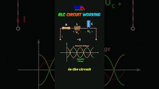
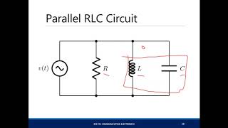
Resonant circuits are fundamental for RF and HF applications, and the resonant frequency is a crucial aspect of their behavior. In a parallel resonant circuit, the inductor and capacitor are connected in parallel, leading to a phenomenon where their reactances cancel each other out at a specific frequency. This frequency is known as the resonant frequency (f₀), calculated using the formula:
$$ f_0 = \frac{1}{2 \pi \sqrt{LC}} $$
This equation highlights the relationship between inductance (L) and capacitance (C), emphasizing that the resonant frequency depends directly on these two components.
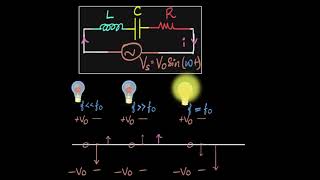
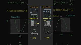
At resonance, the circuit's impedance becomes very high, ideally tending to infinity, meaning that no current flows through the circuit under ideal conditions. In practical scenarios, resistance limits this impedance. The quality of resonance is measured using the Quality Factor (Q), which shows how selective the circuit is around the resonant frequency:
$$ Q = \frac{R}{\sqrt{L/C}} $$
A higher Q indicates sharper resonance and narrower bandwidth, which are critical in applications like filtering and tuning systems. Understanding these properties allows engineers to design effective resonant circuits for precise frequency applications.
Youtube Videos

Key Concepts
-
Resonant Frequency (f₀): The frequency that allows maximum energy transfer in a circuit through impedance matching.
-
Quality Factor (Q): A measure affecting the sharpness and selectivity of the resonance; higher Q results in narrower bandwidth.
-
Impedance: The measure of opposition in an AC circuit, crucial at the point of resonance.
-
Bandwidth (BW): The effective range of frequencies within which the resonant circuit can operate effectively.
Examples & Applications
In tuning radios, engineers optimize the resonant frequency to match the frequency of desired signals, ensuring minimal interference.
High-Q filters are utilized in audio processing, allowing specific frequencies to pass through while minimizing others.
Memory Aids
Interactive tools to help you remember key concepts
Rhymes
At resonance we find the best, high impedance takes the test.
Stories
Imagine a tuning fork in a concert hall; at the right frequency, it vibrates beautifully, silencing all the noise - that’s resonance!
Memory Tools
Remember High Q, Narrow bandwidth can be key!
Acronyms
R.I.P - Resonance In Parallel (to remember resonant frequency in parallel circuits).
Flash Cards
Glossary
- Resonant Frequency (f₀)
The frequency at which a parallel resonant circuit's inductive and capacitive reactances cancel each other, resulting in high impedance.
- Quality Factor (Q)
A measure of the selectivity of a resonant circuit, defining its bandwidth relative to resonant frequency.
- Impedance
The total resistance to current flow in an AC circuit, influenced by resistance, inductance, and capacitance.
- Bandwidth (BW)
The range of frequencies around the resonant frequency where the circuit operates effectively.
Reference links
Supplementary resources to enhance your learning experience.