
Introduction to Resonant Circuits
Interactive Audio Lesson
Listen to a student-teacher conversation explaining the topic in a relatable way.
Introduction to Resonant Circuits
🔒 Unlock Audio Lesson
Sign up and enroll to listen to this audio lesson

Today, we are diving into resonant circuits, critical components in RF and HF designs. Can anyone tell me what they think makes these circuits special?

Is it because they can filter specific frequencies?
Exactly! Resonant circuits are designed to resonate at specific frequencies where inductive and capacitive reactances cancel each other out. This property is what allows for effective frequency selection.

So, how do they actually achieve maximum energy transfer?
Great question! In a series configuration, at resonance, the impedance is minimized, allowing for maximum current flow. It's like having a clear path for electricity.

And in parallel circuits?
In parallel circuits, the impedance is maximized at resonance, which minimizes current flow. This characteristic is useful for specific applications like tuning circuits.

How do we actually use these circuits in real life?
Excellent point! They are widely used in applications like filters, oscillators, and impedance matching in various communication systems.
To recap, resonant circuits are essential for effective frequency selection and energy transfer in communication and electronics. Remember, they can be configured in series or parallel, leading to different behavior at resonance.
Applications of Resonant Circuits
🔒 Unlock Audio Lesson
Sign up and enroll to listen to this audio lesson

Now that we understand resonant circuits, let’s look at where they’re applied. What are some applications you all can think of?
I think they’re used in radios.
Absolutely! They help tune into specific frequencies, making your radio work effectively.
What about amplifying signals in TV?
Correct! Resonant circuits amplify signals within specific frequency ranges, essential for clear transmission in both radio and television.
How do they help in impedance matching?
Good question! They ensure efficient energy transfer between components, like antennas and receivers, maximizing performance. Remember, effective impedance matching is crucial for optimal signal strength.
So, in real-world applications, resonant circuits facilitate communication across various platforms. They play crucial roles in filtering, amplification, and proper energy transfer in circuits.
Significance of Resonant Frequency
🔒 Unlock Audio Lesson
Sign up and enroll to listen to this audio lesson
Let’s delve into the concept of resonant frequency. Who can provide an example of how we calculate this?
Isn’t it based on the inductance and capacitance values?
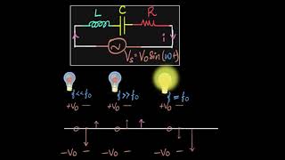
Exactly! The resonant frequency, denoted as f0, is given by the formula: f0 = 1/(2π√(LC)). Can someone explain what L and C represent?
L is inductance and C is capacitance, right?
Correct! Remember, these values determine the frequency at which the circuit resonates. Why is it important for a circuit to resonate at a specific frequency?
So we can filter out unwanted signals?
Exactly! Resonance allows the circuit to effectively amplify specific frequencies while minimizing others. This contributes to better efficiency in signal processing.
To summarize, understanding resonant frequency is critical in designing circuits for various applications, as it directly influences the circuit's performance.
Introduction & Overview
Read summaries of the section's main ideas at different levels of detail.
Quick Overview
Standard
Resonant circuits, also known as LC circuits, play a fundamental role in RF and HF applications. They are designed to resonate at a specific frequency where the inductive and capacitive reactances cancel each other, leading to optimized energy transfer. These circuits are utilized in various applications, including frequency selection, signal amplification, and impedance matching.
Detailed
Introduction to Resonant Circuits
Resonant circuits, often referred to as LC circuits, are integral components in the design of RF (Radio Frequency) and HF (High Frequency) circuits. These circuits are engineered to resonate at a specific frequency, whereby the inductive reactance (
X_L) and capacitive reactance (
X_C) effectively nullify each other.
Key Features of Resonant Circuits
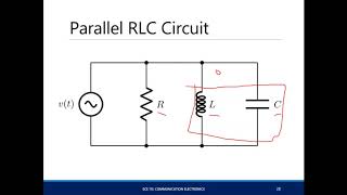
- Impedance Characteristics: In a series resonant circuit, the impedance is minimized, allowing for maximum current flow, whereas in a parallel resonant circuit, the impedance is maximized, minimizing current flow.
- Applications: Resonant circuits are pivotal for frequency selection in filters, enhancing signal amplification in receivers, and achieving efficient impedance matching in communication systems.
Importance in Circuit Design
This chapter will explore the design, analysis, and practical applications of resonant circuits, providing essential knowledge for engineering applications in communication and electronics.
Youtube Videos
Audio Book
Dive deep into the subject with an immersive audiobook experience.
Definition of Resonant Circuits
Chapter 1 of 4
🔒 Unlock Audio Chapter
Sign up and enroll to access the full audio experience
Chapter Content
Resonant circuits, also known as LC circuits, are fundamental in RF and HF circuit design.
Detailed Explanation
Resonant circuits, commonly referred to as LC circuits due to their components, inductors (L) and capacitors (C), play a crucial role in radio frequency (RF) and high frequency (HF) circuit design. These circuits are engineered to resonate at a specific frequency, making them efficient for various applications.
Examples & Analogies
Think of a resonant circuit like a swing. Just as the swing has a natural frequency at which it moves most freely, a resonant circuit has a frequency at which it operates most efficiently, allowing energy to flow easily.
Resonance and Impedance
Chapter 2 of 4
🔒 Unlock Audio Chapter
Sign up and enroll to access the full audio experience
Chapter Content
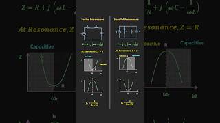
These circuits are designed to resonate at a particular frequency, where the inductive reactance and capacitive reactance cancel each other out. At resonance, the impedance of the circuit is minimized in a series configuration or maximized in a parallel configuration, allowing for maximum energy transfer.
Detailed Explanation
At resonance, the inductive reactance (opposition caused by the inductor) and capacitive reactance (opposition caused by the capacitor) become equal in magnitude but opposite in phase, effectively canceling each other out. This cancellation leads to specific impedance characteristics depending on whether the circuit is configured in series or parallel. In a series configuration, the impedance is minimized, enabling maximum current flow, while in a parallel configuration, the impedance is maximized to reduce current flow.
Examples & Analogies
Imagine an orchestra tuning their instruments. When strings are perfectly in tune (resonance), the sound produced is much clearer and more powerful, similar to how resonant circuits maximize performance at their resonant frequency.
Applications of Resonant Circuits
Chapter 3 of 4
🔒 Unlock Audio Chapter
Sign up and enroll to access the full audio experience
Chapter Content
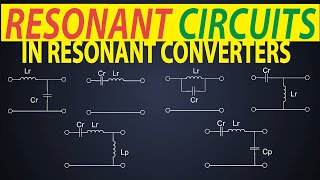
Resonant circuits are widely used in applications such as:
● Frequency selection: Used in filters, oscillators, and tuning circuits.
● Signal amplification: In radio and TV receivers, amplifying signals at specific frequencies.
● Impedance matching: Ensuring efficient energy transfer in antenna and communication systems.
Detailed Explanation
Resonant circuits have several critical applications in electronics. They are key components in frequency selection for filters that allow certain signals to pass while blocking others. They operate in oscillators to generate specific waveforms needed for transmission. Furthermore, resonant circuits facilitate signal amplification in receivers, improving the clarity and strength of signals, and also play a significant role in impedance matching, which is essential for maximizing power transfer in communications systems.
Examples & Analogies
Consider a radio tuner as an example of frequency selection. It uses resonant circuits to match the frequency of the desired radio station, filtering out other frequencies much like how a restaurant filter keeps out unwanted noise so you can enjoy your meal.
Overview of the Chapter
Chapter 4 of 4
🔒 Unlock Audio Chapter
Sign up and enroll to access the full audio experience
Chapter Content
This chapter covers the design, analysis, and practical applications of resonant circuits.
Detailed Explanation
The chapter provides comprehensive insight into resonant circuits, covering their theoretical underpinnings, practical designs, and various applications. Understanding these concepts will arm students with the knowledge necessary to confidently work with resonant circuits in real-world situations.
Examples & Analogies
Think of this chapter as a roadmap on a journey through the world of resonant circuits, where each section helps build your understanding incrementally, leading you to successful navigation in practical scenarios.
Key Concepts
-
Resonant Frequencies: Frequencies at which the inductive and capacitive reactances cancel out, allowing maximum energy transfer.
-
Impedance: The total opposition a circuit presents to alternating current, which varies in resonant circuits based on configuration.
-
Quality Factor (Q): A metric representing the sharpness and selectivity of resonance in a circuit.
Examples & Applications
In radio applications, a resonant circuit may be used to select a specific station's frequency while blocking all others.
In a television receiver, resonant circuits amplify signals in specific frequency bands, ensuring better picture and sound quality.
Memory Aids
Interactive tools to help you remember key concepts
Rhymes
In a circuit where L meets C, resonance flows like a song by the sea.
Stories
Imagine a radio trying to tune into a station. It twists and turns, finding the perfect frequency where sound comes alive. That’s resonance in action!
Memory Tools
Remember 'LCR' for 'Listen, Capacitor, Resonance' to link components with their functions.
Acronyms
Use 'QBS' to recall Quality Factor, Bandwidth, and Selectivity in resonant circuits.
Flash Cards
Glossary
- Resonant Circuit
A type of electrical circuit designed to resonate at a specific frequency, typically consisting of inductors and capacitors.
- Inductive Reactance (X_L)
The opposition to current flow offered by an inductor in an AC circuit, varying with frequency.
- Capacitive Reactance (X_C)
The opposition to current flow offered by a capacitor in an AC circuit, also dependent on frequency.
- Impedance
The total opposition a circuit presents to the flow of AC current, including both resistance and reactance.
- Quality Factor (Q)
A measure of a resonant circuit's selectivity, defined as the ratio of resonant frequency to bandwidth.
- Bandwidth (BW)
The range of frequencies over which a circuit can operate effectively around its resonant frequency.
Reference links
Supplementary resources to enhance your learning experience.