
Summary of Key Concepts
Interactive Audio Lesson
Listen to a student-teacher conversation explaining the topic in a relatable way.
Introduction to Resonant Circuits
🔒 Unlock Audio Lesson
Sign up and enroll to listen to this audio lesson

Today, we're focusing on resonant circuits, vital components in RF and HF applications. Who can explain what a resonant circuit does?

They resonate at a particular frequency where inductive and capacitive reactance cancel each other?
Exactly! This resonance allows us to maximize energy transfer. Can anyone tell me a specific application?

I think they are used in filters and oscillators.
Correct! RF filters and signal amplification are fundamental applications. Remember, these circuits are designed for efficiency in energy transmission.
Types of Resonant Circuits
🔒 Unlock Audio Lesson
Sign up and enroll to listen to this audio lesson

Now that we understand the basics, let’s delve into the two main types of resonant circuits: series and parallel. Who can describe a series resonant circuit?

It's where the inductor and capacitor are connected in series, right?
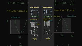
Exactly! At resonance, its impedance is at a minimum, allowing maximum current flow. How does this compare to a parallel resonant circuit?

In a parallel circuit, the impedance is very high at resonance, which minimizes the current flow.
Correct! Remember: Series for maximum current, parallel for maximum impedance.
Designing Resonant Circuits
🔒 Unlock Audio Lesson
Sign up and enroll to listen to this audio lesson
Let’s now talk about designing these circuits. Can anyone tell me the first step in designing a resonant circuit?
Choosing the resonant frequency you want for your application.
Exactly! After selecting the frequency, how do you decide on the inductance and capacitance values?
By using the resonant frequency formula, right?
Right again! This is crucial for achieving optimal performance in your circuit design.
Applications of Resonant Circuits
🔒 Unlock Audio Lesson
Sign up and enroll to listen to this audio lesson
Let’s wrap up by discussing applications. Where do we commonly see resonant circuits utilized?
In tuning circuits, like in radios!
Absolutely! They help select specific frequencies. What are some other applications?
They’re used in filters and oscillators too, right?
Correct! Also in impedance matching for ensuring maximum power transfer.
Introduction & Overview
Read summaries of the section's main ideas at different levels of detail.
Quick Overview
Standard
This section highlights the significance and applications of resonant circuits, outlining the essential characteristics of series and parallel resonant circuits, their design principles, and practical uses in electronics.
Detailed
Resonant circuits, pivotal in RF and HF applications, facilitate efficient signal selection, filtering, and amplification. Series resonant circuits minimize impedance at resonance, making them suitable for applications requiring maximum current flow, while parallel resonant circuits maximize impedance, beneficial for high impedance needs and minimal current. Designing resonant circuits involves careful selection of inductance and capacitance to achieve desired resonant frequency and performance characteristics. Various applications include filters, oscillators, impedance matching, and tuning circuits.
Youtube Videos
Audio Book
Dive deep into the subject with an immersive audiobook experience.
Importance of Resonant Circuits
Chapter 1 of 5
🔒 Unlock Audio Chapter
Sign up and enroll to access the full audio experience
Chapter Content
Resonant Circuits are essential in RF and HF applications, offering efficient signal selection, filtering, and amplification.
Detailed Explanation
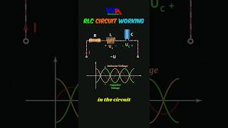
Resonant circuits play a crucial role in radio frequency (RF) and high frequency (HF) applications because they are able to selectively resonate at a specific frequency. This ability allows the circuit to freely pass signals at that frequency while filtering out others, making them highly efficient for applications like communications and broadcasting.
Examples & Analogies
Think of a resonant circuit like a bouncer at a club. The bouncer only allows people (signals) who meet a certain criteria (frequency) to enter, thus ensuring that the environment inside is tailored to a specific experience, much like a specific radio station only plays certain types of music.
Series Resonant Circuits
Chapter 2 of 5
🔒 Unlock Audio Chapter
Sign up and enroll to access the full audio experience
Chapter Content
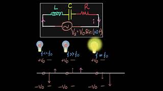
Series Resonant Circuits minimize impedance at resonance and are used in applications requiring maximum current flow.
Detailed Explanation
In a series resonant circuit, when the circuit reaches its resonant frequency, the overall impedance drops to a minimum. This means that the circuit allows maximum current to flow through it. This property is utilized in applications where it's crucial to have a strong current, such as in signal amplification where you want to boost a weak signal.
Examples & Analogies
Imagine a water pipe that narrows down (the circuit's impedance decreases) at a certain point (the resonant frequency). When the pressure of water (current) is increased, it flows very easily through this narrow section, allowing a robust flow, akin to how current flows in a series resonant circuit.
Parallel Resonant Circuits
Chapter 3 of 5
🔒 Unlock Audio Chapter
Sign up and enroll to access the full audio experience
Chapter Content
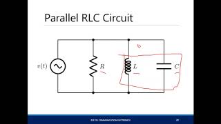
Parallel Resonant Circuits maximize impedance at resonance and are used in applications requiring high impedance and minimal current flow.
Detailed Explanation
In contrast to series resonant circuits, parallel resonant circuits have their impedance at a maximum at resonance. This means these circuits prevent current from flowing freely, making them suitable for applications where you want to limit current flow, like in filters where you only want certain frequencies to pass while blocking others.
Examples & Analogies
Think of a parallel circuit like a road with multiple lanes. At a certain congestion level (resonance), traffic becomes very slow (high impedance) because the cars (current) are not able to flow freely. This restriction is useful for 'filtering' out traffic that doesn't belong on this road.
Designing Resonant Circuits
Chapter 4 of 5
🔒 Unlock Audio Chapter
Sign up and enroll to access the full audio experience
Chapter Content
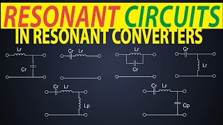
Design of Resonant Circuits involves selecting the right components (inductance and capacitance) to achieve the desired resonant frequency and performance.
Detailed Explanation
The design of resonant circuits is critical because it directly influences how well the circuit performs its intended function. Selecting the right values of inductance (L) and capacitance (C) allows the designer to tune the circuit to resonate at a specific frequency, which in turn affects bandwidth and quality factor (Q).
Examples & Analogies
Consider designing a musical instrument, like a guitar. Choosing the right strings (inductance) and body size (capacitance) determines which notes can be produced clearly. If you pick suitable components, the instrument resonates beautifully at the intended frequencies.
Applications of Resonant Circuits
Chapter 5 of 5
🔒 Unlock Audio Chapter
Sign up and enroll to access the full audio experience
Chapter Content
Applications of resonant circuits include filters, oscillators, impedance matching, and tuning circuits.
Detailed Explanation
Resonant circuits are widely utilized in various applications, including filters that enhance or suppress certain frequencies, oscillators that generate continuous waveform signals, and tuning circuits that allow for the selection of specific frequencies to improve communication quality. They are also involved in impedance matching circuits to ensure that maximum power is transferred between different circuit elements.
Examples & Analogies
Imagine tuning a radio to find your favorite station. The radio uses resonant circuits to focus on the station's frequency, filtering out static and interference, similar to how a well-tuned musical instrument brings the right notes to life while muting the wrong ones.
Key Concepts
-
Resonant Circuits: Essential components in RF applications for signal selection and amplification.
-
Series Resonant Circuit: Minimizes impedance at resonance, maximizing current flow.
-
Parallel Resonant Circuit: Maximizes impedance at resonance, minimizing current flow.
-
Design Principles: Selecting inductance and capacitance values based on desired resonant frequency.
-
Applications: Filters, oscillators, impedance matching, and tuning circuits.
Examples & Applications
A series resonant circuit is commonly found in radio transmitters to deliver a maximum signal to the antenna.
A parallel resonant circuit is often utilized in guitar amplifiers to ensure specific tones are amplified through resonance.
Memory Aids
Interactive tools to help you remember key concepts
Rhymes
In series circuits, impedance drops low, maximizing current, letting energy flow.
Stories
Imagine a race where two runners compete: one in a narrow lane (series) runs fast while the other in a broad lane (parallel) runs slow. The narrower path symbolizes lower impedance in a series circuit, allowing for steadier, faster currents!
Memory Tools
Remember 'S+P': Series for Power (current) and Parallel for Peak (impedance).
Acronyms
Q stands for Quality
Quick in bandwidth
Quicker in response!
Flash Cards
Glossary
- Resonant Circuit
A circuit designed to resonate at a specific frequency where inductive and capacitive reactances cancel each other.
- Impedance
The total opposition a circuit presents to the flow of alternating current, measured in ohms.
- Resonant Frequency
The frequency at which a resonant circuit naturally oscillates.
- Quality Factor (Q)
A dimensionless parameter that describes how underdamped a resonant circuit is, indicating the selectivity of the circuit.
- Bandwidth
The range of frequencies over which a resonant circuit operates effectively.
Reference links
Supplementary resources to enhance your learning experience.