
Step 2: Choose Components - 3.3.2.2
Interactive Audio Lesson
Listen to a student-teacher conversation explaining the topic in a relatable way.
Understanding Resonant Frequency
🔒 Unlock Audio Lesson
Sign up and enroll to listen to this audio lesson

Today, we're discussing how to choose components for our resonant circuits. First, can anyone tell me what resonant frequency means?

Isn't it the frequency at which the circuit resonates?
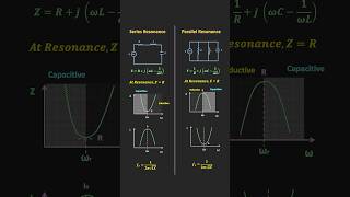
Exactly! It's represented by the formula f₀ = 1/(2π√(LC)). This shows the relationship between inductance and capacitance. Can you explain what happens at this frequency?

At that frequency, the reactance from the inductor and capacitor cancel each other out, right?
Yes! This is crucial because it determines how the circuit will respond. Remember the acronym LCR: Inductor, Capacitor, Resonance. It can help you recall the key components involved.

So, if we change L or C, the resonant frequency will also change?
That's correct! Keeping track of these relationships is vital for circuit design. Let's summarize: The resonant frequency is driven by L and C values, impacting how the circuit behaves.
Choosing Correct Components
🔒 Unlock Audio Lesson
Sign up and enroll to listen to this audio lesson

Now that we understand resonant frequency, let’s explore how to choose L and C. What should we consider?

We need to find components that fit our calculated values, right?
Absolutely! It’s essential to work with commercially available components. What factors might affect our choice?
The values we calculate might not always be available exactly.
Good point! You might have to adjust your design slightly. Each choice of L and C has consequences for the bandwidth and quality factor. Let’s remember ‘BQC’—Bandwidth, Quality, Components.
How do bandwidth and quality factor relate to our component choice?
Bandwidth shows how broad the frequencies are where your circuit operates effectively, while quality factor indicates selectivity. Let’s summarize: Choosing the right L and C values affects both the performance and characteristics of the resonant circuit.
Testing and Verification
🔒 Unlock Audio Lesson
Sign up and enroll to listen to this audio lesson
Finally, after we've selected our values for L and C, what's the next step?
We have to test the circuit, right?
That's right! Simulation allows us to verify that the circuit behaves as expected. What’s something important we should look for during testing?
Checking if the resonant frequency matches our calculations!
Exactly! And make sure the bandwidth and quality factor are in the expected ranges as well. Remember the phrase ‘VBS’—Verify, Bandwidth, Simulate. Can anyone summarize our testing process?
We select components, simulate, and check for alignment with our design goals like resonant frequency!
Well done! Testing is a key step in circuit design, ensuring our selections lead to successful outcomes.
Introduction & Overview
Read summaries of the section's main ideas at different levels of detail.
Quick Overview
Standard
In this section, key steps for designing resonant circuits are outlined, emphasizing the selection of suitable inductance and capacitance values based on the desired resonant frequency. The resonant frequency is determined using a specific formula, and the interplay between these components and the resultant circuit characteristics—including bandwidth and quality factor—is discussed.
Detailed
Detailed Summary
In designing resonant circuits, selecting the right components, particularly inductance (L) and capacitance (C), is crucial in achieving the desired resonant frequency (f₀). The resonant frequency, defined by the equation:
$$f_0 = \frac{1}{2\pi\sqrt{LC}}$$
is central to effective circuit operation. The selection process involves considering commercially available components that match the calculations for L and C based on the targeted resonant frequency.
In addition to choosing L and C, understanding the impact of these values on the circuit's overall performance is critical. The bandwidth (BW) and the quality factor (Q), which are influenced by the resistance (R) and determine the selectivity of the circuit, must also be calculated. Higher Q values indicate sharper resonance, suggesting a more selective circuit. The section reinforces the importance of simulating the circuit post-selection to verify that the performance aligns with design expectations.
Youtube Videos
Audio Book
Dive deep into the subject with an immersive audiobook experience.
Calculating Component Values
Chapter 1 of 2
🔒 Unlock Audio Chapter
Sign up and enroll to access the full audio experience
Chapter Content
Based on the resonant frequency, calculate the L and C values using the resonant frequency equation.
Detailed Explanation
To choose the right components for a parallel resonant circuit, it's essential to first calculate the inductance (L) and capacitance (C) values. This is done using the formula for resonant frequency, which relates these two components to the desired frequency where the circuit will resonate. The equation is given by f_0 = 1/(2π√(LC)). Here, f_0 is the resonant frequency. By rearranging this equation, you can solve for either L or C if one of the values is known.
Examples & Analogies
Think of it like planning a party where you need a specific number of guests to fit comfortably in a room. If you know the room size (the frequency), you can calculate how many chairs (inductors) and tables (capacitors) you need to fit everyone comfortably without crowding.
Selecting Suitable Values of L and C
Chapter 2 of 2
🔒 Unlock Audio Chapter
Sign up and enroll to access the full audio experience
Chapter Content
Select suitable values of L and C that are commercially available.
Detailed Explanation
After calculating the required L and C values to achieve the desired resonant frequency, the next step is to find components that are available for purchase. It's important that these components match or closely approximate the calculated values. This can involve checking specifications from manufacturers or suppliers to ensure that the components will work correctly in the circuit.
Examples & Analogies
Imagine you're shopping for groceries and you have a specific recipe in hand that requires certain ingredients. You know exactly what you need, but you must check the shelves to find items that match the quantities and types specified in your recipe.
Key Concepts
-
Inductance (L): A measure of a circuit's ability to store energy in a magnetic field.
-
Capacitance (C): A measure of a circuit's ability to store energy in an electric field.
-
Resonant Frequency (f₀): The frequency at which the circuit resonates, determined by L and C.
-
Quality Factor (Q): Indicates how selectively the circuit responds to the resonant frequency.
-
Bandwidth (BW): The effective frequency range in which the circuit operates.
Examples & Applications
If a resonant circuit is designed with a 10 μH inductor and a 100 nF capacitor, the resonant frequency calculated is approximately 159.15 kHz.
For a quality factor of 10 in a circuit, if the resonant frequency is 1 MHz, the bandwidth would be determined using the equation BW = f₀/Q, yielding a bandwidth of 100 kHz.
Memory Aids
Interactive tools to help you remember key concepts
Rhymes
In circuits where forces seem to cope, Inductance and capacitance helps us hope. Resonance peaks come clear and bright, L and C must always fit right.
Stories
Picture a race between two friends, Inductor and Capacitor. They must work together to resonate at a perfect frequency to win the race against distortion. Choosing L and C wisely leads them to the finish line!
Memory Tools
Remember 'LC-FRQ' for Inductance, Capacitance, and Frequency relationship in resonance.
Acronyms
QBC—Quality, Bandwidth, Components—helps you recall the factors to consider while designing resonant circuits.
Flash Cards
Glossary
- Resonant Frequency (f₀)
The frequency at which the inductive and capacitive reactances in a circuit cancel each other, resulting in zero net reactance.
- Inductance (L)
A property of an electrical component that quantifies its ability to store energy in a magnetic field.
- Capacitance (C)
A property of an electrical component that quantifies its ability to store energy in an electric field.
- Quality Factor (Q)
A dimensionless parameter that measures the selectivity of a resonant circuit; higher values indicate a sharper resonance.
- Bandwidth (BW)
The range of frequencies over which the resonant circuit operates effectively, determined by component values.
Reference links
Supplementary resources to enhance your learning experience.