
Impedance at Resonance - 3.2.1.1
Interactive Audio Lesson
Listen to a student-teacher conversation explaining the topic in a relatable way.
Understanding Impedance at Resonance
🔒 Unlock Audio Lesson
Sign up and enroll to listen to this audio lesson

Today, we're going to talk about impedance at resonance, particularly how it behaves in series resonant circuits. Can anyone tell me what we understand by impedance?

Isn't it the opposition that a circuit presents to the flow of alternating current?
Exactly! Impedance is indeed that opposition. Now, at resonance in a series resonant circuit, the inductive and capacitive reactances cancel each other out. What does that mean for our total impedance?

Oh! So the impedance becomes purely resistive, right?
Correct! And that is expressed by the formula: Z_resonance = R. This means that at resonance, the circuit allows maximum current to flow.

So, if we were to look at the values of the inductive and capacitive reactances, they would be equal?
Yes! And do you remember the formulas we can use to describe resonance frequency?

It's f_0 = 1/(2π√(LC)).
Excellent! Remember this formula as it directly ties to how we design and analyze resonant circuits.
In summary, at resonance, the impedance is minimized in series hubs and can be maximized or even infinite in parallel circuits based on conditions.
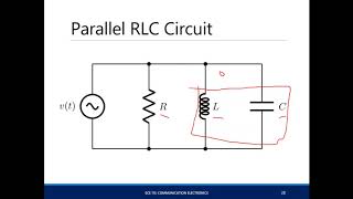
Impedance in Parallel Resonant Circuits
🔒 Unlock Audio Lesson
Sign up and enroll to listen to this audio lesson

Now, let's shift our focus to parallel resonant circuits. Remember our discussion on series resonance? How does impedance behave differently in parallel?
In parallel, doesn't it aim for maximum impedance instead?
That's right! At resonance, the ideal impedance in a parallel resonant circuit can be considered infinite when reactances cancel. But in practical scenarios, what limitations do we face?
The resistance of the inductor or losses in the circuit can lower that impedance, right?
Exactly! When designing these circuits, we need to consider real-world components. Looking at the same resonant frequency formula, who can recall it?
That's still f_0 = 1/(2π√(LC)), right?
Correct! The resonant frequency does not change between series and parallel circuits, which is a crucial point. Now, how about bandwith and Q factor in parallel circuits?
Isn't the Q factor related to how sharply the circuit resonates?
Yes! The quality factor Q measures selectivity. For parallel circuits, we express this as Q = f_0/BW = R/√(L/C). A higher Q means sharper resonance. Let's wrap up this session!
Today, we covered the differences in impedance between parallel and series resonant circuits and the significance of the resonant frequency.
Applications and Importance of Resonant Circuits
🔒 Unlock Audio Lesson
Sign up and enroll to listen to this audio lesson
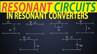
In our last session on impedance, let's discuss real-world applications of resonant circuits. Who can think of a situation where this might apply?
I think about radio receivers. They must select specific frequencies using resonance!
Great example! Resonant circuits are deeply embedded in RF applications, allowing for efficient signal amplification. Can anyone think of another area?
Filters! They use resonant circuits to allow certain frequencies and block others!
Absolutely right! Filters are fundamental in communications and audio electronics. Remember, by understanding impedance at resonance, we achieve efficient designs.
How frequent is the application in impedance matching?
Excellent question! It ensures maximum power transfer between stages of circuits, maintaining signal integrity. All right, to summarize, we explored applications of resonance and their importance in circuit design.
Introduction & Overview
Read summaries of the section's main ideas at different levels of detail.
Quick Overview
Standard
This section discusses the concept of impedance at resonance for series and parallel resonant circuits, detailing how the total impedance is affected by the relationship between inductive and capacitive reactances, and defines key formulas related to resonant frequency, bandwidth, and quality factor.
Detailed
Impedance at Resonance
Impedance Overview
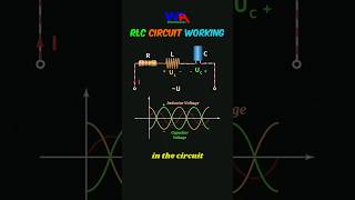
At resonance in a series resonant circuit, the inductive reactance (
$X_L$) and capacitive reactance (
$X_C$) equal each other, creating a purely resistive circuit where the total impedance (
$Z$) is simply the resistance (
$R$) of the circuit. The formula is:
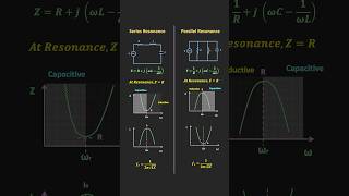
$$Z_{resonance} = R$$
In contrast, for a parallel resonant circuit, the impedance becomes infinite at resonance under ideal conditions since the reactances cancel out. Practically, resistance limits this impedance:
$$Z_{resonance} = ∞ ext{ (ideal)}$$
Resonant Frequency
The resonant frequency (
$f_0$) can be calculated for both series and parallel circuits using the same formula:
$$f_0 = \frac{1}{2 \pi \sqrt{LC}}$$
where
$L$ is inductance and
$C$ is capacitance.
Bandwidth and Quality Factor (Q)
The bandwidth (B) describes the effective range of frequencies around resonance, impacted by the resistance in the circuit, expressed as:
$$BW = \frac{R}{L}$$
The quality factor (
$Q$) measures the sharpness of resonance:
-
For series circuits:
$$Q = \frac{f_0}{BW} = \frac{L}{CR}$$ -
For parallel circuits:
$$Q = \frac{f_0}{BW} = \frac{R}{\sqrt{L/C}}$$
A higher Q indicates a narrower bandwidth, useful for achieving selective resonance. In summary, understanding impedance at resonance is fundamental for the design and application of resonant circuits in various electronic systems.
Youtube Videos
Audio Book
Dive deep into the subject with an immersive audiobook experience.
Understanding Impedance at Resonance
Chapter 1 of 2
🔒 Unlock Audio Chapter
Sign up and enroll to access the full audio experience
Chapter Content
At resonance, the inductive reactance \( X_L \) and capacitive reactance \( X_C \) are equal and opposite, resulting in zero net reactance. The total impedance \( Z \) of the circuit is simply the resistance \( R \) of the resistor (or equivalent resistance in case of practical components).
\[ Z_{resonance} = R \]
Detailed Explanation
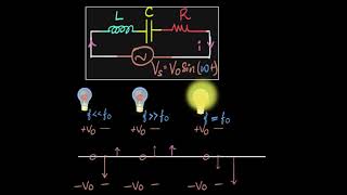
In a series resonant circuit, resonance occurs when the energy stored in the inductor is equal to the energy stored in the capacitor. At this point, the inductive reactance, which opposes changes in current, cancels out the capacitive reactance, which opposes changes in voltage. This cancellation means that there is no reactance left to oppose the flow of current, and the total impedance is purely resistive, represented by the resistance \( R \) alone.
Examples & Analogies
Think of a swing at a playground. When a child pushes the swing at just the right moment (this timing is like finding the resonant frequency), the swing goes higher and higher without much effort. However, if they push it at the wrong moments (out of resonance), the swing doesn’t move much. Similarly, at resonance in a circuit, the flow of electrical energy is maximized, just as the swing's height is maximized with proper timing.
Practical Implications of Impedance at Resonance
Chapter 2 of 2
🔒 Unlock Audio Chapter
Sign up and enroll to access the full audio experience
Chapter Content
This condition allows for maximum energy transfer, making series resonant circuits effective in applications requiring high current flow and minimal losses at the resonant frequency.
Detailed Explanation
When the impedance is minimized at resonance, it facilitates maximum energy transfer from the power source to the load (devices, antennas, etc.). This characteristic is especially important in applications like radio transmitters, where efficient power use is critical. Engineers design circuits that operate exactly at this resonance point to ensure that they can deliver as much power as possible, minimizing wasted energy and maximizing performance.
Examples & Analogies
Imagine trying to pour syrup from a bottle. If you tip the bottle just right (similar to being at resonance), the syrup flows out smoothly without getting stuck. But if you don't tilt it enough or tip it too far, the flow is either too slow or spills everywhere. In electrical terms, minimizing impedance at resonance allows current to flow smoothly, just like the syrup flows when the bottle is correctly tilted.
Key Concepts
-
Impedance at Resonance: The total opposition to current flow in the circuit becomes minimal in series circuits and maximal in parallel circuits at the resonant frequency.
-
Resonant Frequency (f0): The frequency at which resonance occurs, calculated as 1/(2π√(LC)).
-
Quality Factor (Q): A significant measure of how sharp or selective the resonance effect is within a circuit.
-
Bandwidth (BW): The effective range of frequencies around the resonant frequency.
Examples & Applications
When designing a radio receiver, engineers set the resonant frequency of the LC circuit to match the target signal frequency for optimal reception.
In audio equipment, equalizers use resonant circuits to boost or cut certain frequency ranges, enhancing sound quality.
Memory Aids
Interactive tools to help you remember key concepts
Rhymes
Impedance is key, when circuits align, series goes low, while parallel’s divine.
Stories
Imagine a circuit at a concert where each musician needs to play in harmony. When they hit the resonant frequency, it’s like everyone plays perfectly together, maximizing the sound—much like impedance at resonance.
Memory Tools
PIE for impedance: P for peak (maximum), I for impedance, and E for energy transfer at resonance.
Acronyms
R-FIZ
for Resonant
for Frequency
for Impedance
for Zero net reactance in series.
Flash Cards
Glossary
- Impedance
The total opposition that a circuit presents to the flow of alternating current, encompassing both resistance and reactance.
- Resonance
The condition in which inductive and capacitive reactances are equal, resulting in a purely resistive circuit at a specific frequency.
- Resonant Frequency (f0)
The frequency at which resonance occurs, calculated using the formula f0 = 1/(2π√(LC)).
- Quality Factor (Q)
A measure of the selectivity or sharpness of the resonance, calculated as the ratio of resonant frequency to bandwidth.
- Bandwidth (BW)
The range of frequencies around the resonant frequency at which the circuit operates effectively.
Reference links
Supplementary resources to enhance your learning experience.