
Step 1: Select the Resonant Frequency - 3.3.2.1
Interactive Audio Lesson
Listen to a student-teacher conversation explaining the topic in a relatable way.
Understanding Resonant Frequency
🔒 Unlock Audio Lesson
Sign up and enroll to listen to this audio lesson

Today, we're going to discuss how to select the resonant frequency for parallel resonant circuits. Does anyone have a guess about why resonant frequency is important?

I think it helps in tuning the circuit to the right signal or frequency.
That's absolutely right! The resonant frequency is crucial for tuning into specific signals. It plays a vital role in the circuit's functionality. Can anyone tell me the formula for resonant frequency?

Is it f_0 = 1/(2π√(LC))?
Exactly! Remember, where L is the inductance and C is the capacitance. This relationship shows how both components affect the circuit's performance. Let's make sure we remember: The more inductance or capacitance we have, the lower the frequency will be.
Factors Influencing Selection
🔒 Unlock Audio Lesson
Sign up and enroll to listen to this audio lesson

Now that we understand the formula, what factors do you think might influence our choice of f_0?

I guess it depends on what frequency we want to filter or amplify.
Correct! The specific application dictates the resonant frequency. For instance, in tuning circuits, we want to select frequencies that match specific broadcasting stations. What's another consideration?

The components we can get hold of, right? We need to use commercially available L and C values.
Exactly! It's essential to ensure that the selected values are practical and available for your project. Remember, L and C not only determine f_0 but can also affect the quality factor and bandwidth of your circuit.
Practical Application of Resonant Frequency
🔒 Unlock Audio Lesson
Sign up and enroll to listen to this audio lesson
Let's apply what we've learned. Imagine we're building a radio receiver. What resonant frequency would we choose for a station at 101.1 MHz?
We'd have to use the formula to find L and C values that resonate at that frequency!
Can't we adjust L or C to create a tuning effect?
Absolutely! By adjusting either component, you’d effectively change the resonant frequency. This is how tuning circuits allow you to sift through various stations. Remember, having a precise resonant frequency is key to good performance in communication systems.
Introduction & Overview
Read summaries of the section's main ideas at different levels of detail.
Quick Overview
Standard
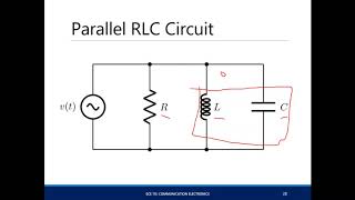
Selecting the resonant frequency is the first step in designing parallel resonant circuits. This frequency is essential for ensuring proper functionality in various applications, including tuning and filtering. The relationship between the resonant frequency and the values of inductance and capacitance must be understood and calculated accurately.
Detailed
Step 1: Select the Resonant Frequency
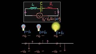
In designing a parallel resonant circuit, selecting the resonant frequency ( fo ) is critical to meet specific application requirements. The resonant frequency defines at which frequency the circuit will operate optimally, allowing it to perform tasks such as tuning into specific signals, filtering frequencies, or matching impedance. The basic relationship governing this frequency is given by the equation:
_0 = rac{1}{2 \pi \sqrt{LC}}
Where L is the inductance and C is the capacitance of the circuit. The selection of f_0 is contingent on the application's needs, whether it's for filtering out unwanted signals or amplifying desired frequencies. Therefore, accurately selecting the resonant frequency is the foundational step in achieving the desired performance and efficiency in parallel resonant circuit design.
Youtube Videos
Audio Book
Dive deep into the subject with an immersive audiobook experience.
Decide on the Desired Resonant Frequency
Chapter 1 of 2
🔒 Unlock Audio Chapter
Sign up and enroll to access the full audio experience
Chapter Content
Decide the desired resonant frequency f0_f0 for your application (e.g., a specific radio frequency, or a target frequency for a filter).
Detailed Explanation
In this first step of the design process, you need to determine what frequency you want your resonant circuit to operate at. This frequency, called the resonant frequency (denoted as f0), will be the specific point where the circuit works most effectively. For instance, if you are designing a radio receiver, you may choose the specific frequency of a radio station you want to tune into.
Examples & Analogies
Think of selecting a resonant frequency like choosing a specific TV channel. Just like you pick a channel to watch your favorite show, in circuit design, you select a frequency where the circuit will 'watch' or pick up signals most efficiently.
Applications of Resonant Frequency
Chapter 2 of 2
🔒 Unlock Audio Chapter
Sign up and enroll to access the full audio experience
Chapter Content
For example, a specific radio frequency, or a target frequency for a filter.
Detailed Explanation
When you have decided on a resonant frequency, it is important to know the application of that frequency. Depending on whether you're designing a filter, an oscillator, or any other device, the chosen frequency will guide how you proceed in selecting materials and components in the circuit design. This choice affects the behavior and efficiency of the resonant circuit.
Examples & Analogies
Consider it like planning a road trip. Your destination (the chosen frequency) dictates your route (the design choices you make) and what you will need for the trip (the components you select) to reach that destination smoothly.
Key Concepts
-
Resonant Frequency: The frequency at which the circuit resonates and operates most efficiently.
-
Inductance and Capacitance: The two components that determine the resonant frequency of a circuit.
-
Application: The desired frequency in a circuit often dictates the choice of inductance and capacitance.
Examples & Applications
For a parallel resonant circuit intended for Radio Frequency Identification (RFID) applications, the resonant frequency must be calculated to match the operating frequency of RFID tags, often around 13.56 MHz.
In designing a mobile communication device that operates at 850 MHz, the inductor and capacitor values must be selected to yield a resonant frequency that matches this frequency for proper functioning.
Memory Aids
Interactive tools to help you remember key concepts
Rhymes
For a circuit to resonate, don't miss the cue, choose L and C just right, or signals won’t come through!
Stories
Imagine a radio tuned perfectly to your favorite station, ensuring clear sound. Just like adjusting L and C elements helps tune into specific frequencies, a good radio has precise settings to deliver the best sound.
Memory Tools
Remember 'L-C' stands for 'Low circuits' when tuning; higher L means lower frequency is what you're pursuing.
Acronyms
R-F-C
Resonant Frequency Calculation - Always consider what frequency is critical for your application.
Flash Cards
Glossary
- Resonant Frequency
The frequency at which a resonant circuit operates optimally, defined as f_0 = 1/(2π√(LC)).
- Inductance (L)
The property of a circuit that opposes changes in current, typically measured in henries (H).
- Capacitance (C)
The ability of a component to store electrical energy, typically measured in farads (F).
- Quality Factor (Q)
A measure of the selectivity of a resonant circuit, indicating how sharply the circuit can resonate at its frequency.
Reference links
Supplementary resources to enhance your learning experience.