
Design of Resonant Circuits
Interactive Audio Lesson
Listen to a student-teacher conversation explaining the topic in a relatable way.
Selecting Resonant Frequency
🔒 Unlock Audio Lesson
Sign up and enroll to listen to this audio lesson

Today, we'll discuss how to start the design of a resonant circuit. Can anyone tell me what the first step is?

Is it deciding what components to use?
Not quite! The first step is to select the desired resonant frequency, f0. This frequency will be paramount in determining how the circuit behaves in its application.

How do we choose the right frequency?
Great question! The frequency is usually based on the specific application, like a radio frequency. Remember the acronym RESONATE: **R**eflect, **E**stablish, **S**elect, **O**ptimize, **N**eed, **A**ct, **T**est, **E**valuate. This will help recall the steps of designing a resonant circuit.

What if the frequency is too high or low?
Adjusting the values of inductance and capacitance will help achieve the desired frequency at later stages.
So, what's the first thing we do in designing a resonant circuit?

Select the resonant frequency based on the application!
Exactly! Well done. Let's move on.
Choosing Components
🔒 Unlock Audio Lesson
Sign up and enroll to listen to this audio lesson

Now that we've chosen the resonant frequency, what's next?
Do we select components now?
Yes! We need to calculate L and C using the resonant frequency formula. Can anyone recall that formula?
It's f0 = 1/(2π√(LC)).
Correct! So, if I want—for example—f0 to be 1 kHz, how do we rearrange the formula to find L or C?
We could isolate L or C and plug in values!
Exactly! For practical designs, you’d select commercially available values for L and C once you have your calculations. Can you think of where we might find these components?
Electronic component stores or online retailers must have those.
Exactly! Great job, everyone. Choosing the right components is critical.
Calculating Bandwidth and Quality Factor
🔒 Unlock Audio Lesson
Sign up and enroll to listen to this audio lesson
Next, we need to understand bandwidth and quality factor. Does anyone have a basic idea of what bandwidth refers to in a resonant circuit?
Isn't it the range of frequencies around f0?
Correct! The bandwidth is determined by the resistance we incorporate. Perhaps you remember the equation for quality factor, Q?
Q = f0/BW, right?
Yes, precisely! A higher Q indicates a narrower bandwidth, which can be useful in selective applications. Let's use an example: if f0 is 1 kHz and BW is 10 Hz, what's our Q?
That would be 100.
Excellent! Adjusting R can help meet the desired Q for our application.
Verifying Performance
🔒 Unlock Audio Lesson
Sign up and enroll to listen to this audio lesson
Finally, after choosing the components, verifying performance is critical. Why do you think we need to simulate the circuit?
To see if it works as expected?
Exactly! Simulations confirm that our theoretical calculations translate well to real-world performance. What tools might we use for this?
Circuit simulation software like SPICE?
Well done! If something doesn't match expectations, we can adjust values and re-test before finalizing the design.
So what did we learn about verifying the performance?
That simulating helps ensure everything works as intended!
Well summarized! This completes our session on designing resonant circuits.
Introduction & Overview
Read summaries of the section's main ideas at different levels of detail.
Quick Overview
Standard
The design of resonant circuits involves selecting appropriate inductance and capacitance values to achieve a desired resonant frequency and quality factor. Key steps include choosing components, calculating bandwidth, and verifying performance through simulations.
Detailed
Design of Resonant Circuits
Designing resonant circuits is crucial for achieving specific frequency behaviors and ensuring optimal operation in applications like filters and oscillators. As such, the main steps involved in designing both series and parallel resonant circuits are:
- Select the Resonant Frequency: Establish the target resonant frequency for the circuit, dictated by the application needs.
- Choose Components: Calculate the values of inductance (L) and capacitance (C) using the resonant frequency formula:
$$ f_0 = \frac{1}{2 \pi \sqrt{LC}} $$
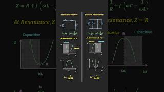
- Calculate the Bandwidth and Quality Factor: Depending on the resistance, the bandwidth (BW) and quality factor (Q) should be computed to meet operational requirements. A high Q signifies a narrow bandwidth, beneficial for certain applications.
- Verify Performance: After components are selected, simulations must be conducted to validate the circuit's expected performance and adjust component values as necessary.
This guidance applies to both series and parallel resonant configurations, making it a fundamental concept in RF and HF circuit design.
Youtube Videos

Audio Book
Dive deep into the subject with an immersive audiobook experience.
Overview of Designing Resonant Circuits
Chapter 1 of 3
🔒 Unlock Audio Chapter
Sign up and enroll to access the full audio experience
Chapter Content
Designing resonant circuits involves selecting the right combination of inductance and capacitance to achieve the desired resonant frequency and quality factor. The steps in designing a resonant circuit are as follows:
Detailed Explanation
In this opening chunk, we learn that the design of resonant circuits is not arbitrary but revolves around two main components: inductors (L) and capacitors (C). The goal is to achieve a specified resonant frequency (f0) and quality factor (Q). The design process is systematic and involves several specific steps to ensure the circuit functions as intended, emphasizing the importance of selecting the appropriate values for L and C based on the desired characteristics of the circuit.
Examples & Analogies
Think of designing a resonant circuit like tuning a musical instrument. Just as a musician adjusts the tension of strings or the lengths of tubes to achieve the correct pitch, an engineer adjusts inductance and capacitance values to get the desired resonant frequency.
Series Resonant Circuit Design Steps
Chapter 2 of 3
🔒 Unlock Audio Chapter
Sign up and enroll to access the full audio experience
Chapter Content
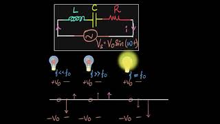
3.3.1 Series Resonant Circuit Design
- Step 1: Select the Resonant Frequency
Decide the desired resonant frequency f0 for your application (e.g., a specific radio frequency, or a target frequency for a filter). - Step 2: Choose Components
Based on the desired resonant frequency, calculate the values of L and C using the resonant frequency equation:
f0=12πLC
Select suitable values of L and C that are commercially available. - Step 3: Calculate the Bandwidth and Quality Factor
Using the Q factor equation, select an appropriate resistor value to ensure that the bandwidth is suitable for your application. A higher Q results in a narrower bandwidth, which is useful in applications such as selective filters. - Step 4: Verify Performance
After selecting components, simulate the circuit to verify its performance and adjust component values if necessary.
Detailed Explanation
This chunk outlines the steps to design a series resonant circuit. First, you need to select the resonant frequency based on the application's needs. Next, you calculate and select appropriate inductance and capacitance values that will produce that frequency. Following this, you'll need to determine the bandwidth and quality factor, which will guide the selection of resistance. Finally, it's crucial to simulate the circuit to check that everything functions correctly and make adjustments as required.
Examples & Analogies
Imagine you are planning a birthday party and want to choose a theme (resonant frequency). You then decide the decoration styles and colors (inductance and capacitance) that match your theme. You might need to calculate how much food (bandwidth) you will need based on the number of guests (quality factor). Finally, you run through the party plan to make sure everything will go smoothly (verifying performance).
Parallel Resonant Circuit Design Steps
Chapter 3 of 3
🔒 Unlock Audio Chapter
Sign up and enroll to access the full audio experience
Chapter Content
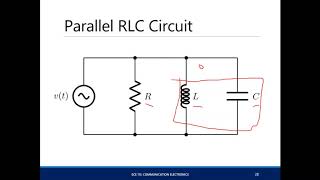
3.3.2 Parallel Resonant Circuit Design
- Step 1: Select the Resonant Frequency
As with series circuits, decide on the desired resonant frequency f0. - Step 2: Choose Components
Based on the resonant frequency, calculate the L and C values using the resonant frequency equation. - Step 3: Calculate the Quality Factor and Bandwidth
Select the parallel resistance value to achieve the desired bandwidth. The Q factor determines the selectivity of the resonance and can be adjusted based on the circuit's requirements. - Step 4: Verify Performance
After component selection, simulate the circuit and verify that the resonance and bandwidth are as desired.
Detailed Explanation
This chunk provides the steps required to design a parallel resonant circuit. Similar to series circuits, you start by selecting the resonant frequency. After that, you need to compute the values of inductance and capacitance based on this frequency. The design also includes setting the parallel resistance to achieve the desired bandwidth, which is a balance between selectivity and frequency response. Finally, just as with series circuits, simulating the circuit helps ensure desired performance.
Examples & Analogies
Designing a parallel resonant circuit can be likened to organizing a committee. You start with a goal or theme (resonant frequency) and then choose members (components) based on their skills. The selectivity (quality factor) of the committee’s decisions depends on how closely they can work together (bandwidth). After setting everything up, you could run a mock meeting to see if your chosen team can achieve the goals you set (verifying performance).
Key Concepts
-
Resonant Frequency: The specific frequency at which a resonant circuit operates effectively.
-
Inductor and Capacitor: The primary components of resonant circuits that store energy.
-
Quality Factor (Q): A measure of the sharpness of resonance, impacting selectivity.
-
Bandwidth: The range of frequencies over which the circuit can function effectively.
Examples & Applications
Example of a series resonant circuit: Can be used as a band-pass filter to isolate a specific frequency from a signal.
Example of a parallel resonant circuit: Found in radio receivers to pick a specific station from all frequencies.
Memory Aids
Interactive tools to help you remember key concepts
Rhymes
To design a circuit that's just right, choose L and C with all your might.
Stories
Imagine a radio station tuning into a specific frequency: it carefully balances inductance and capacitance to resonate perfectly, avoiding noise.
Memory Tools
Remember the steps to design: Select, Calculate, Check, Simulate - S, C, C, S!
Acronyms
Use the acronym RAD to remember the process
**R**esonant frequency
**A**cquire components
**D**esign and verify.
Flash Cards
Glossary
- Resonant Frequency (f0)
The frequency at which a circuit naturally resonates, determined by the values of inductance (L) and capacitance (C).
- Inductance (L)
The property of a circuit that opposes changes in current and is measured in henries (H).
- Capacitance (C)
The ability of a component to store electrical energy in an electric field, measured in farads (F).
- Quality Factor (Q)
A dimensionless parameter that characterizes how underdamped an oscillator or resonator is, indicating its selectivity.
- Bandwidth (BW)
The range of frequencies over which the circuit operates effectively around the resonant frequency.
Reference links
Supplementary resources to enhance your learning experience.