
Applications of Bernoulli's Equation
Enroll to start learning
You’ve not yet enrolled in this course. Please enroll for free to listen to audio lessons, classroom podcasts and take practice test.
Interactive Audio Lesson
Listen to a student-teacher conversation explaining the topic in a relatable way.
Understanding Bernoulli's Equation
🔒 Unlock Audio Lesson
Sign up and enroll to listen to this audio lesson

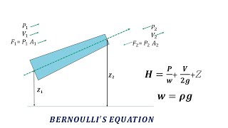
Today, we will discuss Bernoulli's Equation, which relates the velocity, pressure, and height of a fluid at different points. Can anyone tell me how this applies to fluid flow in pipes?

Isn't it used to predict the pressure changes in fluid flowing through a pipe?
Correct! Bernoulli’s equation helps us understand how fluid gains or loses pressure as it flows through different cross-sections in a pipe. Remember the acronym P-V-H, which stands for Pressure, Velocity, and Height. This helps to recall its components.

What about the losses mentioned in the equation?
Excellent question! These losses can be classified into major losses, which are due to friction, and minor losses, from fittings like bends and valves. We'll explore these in detail in later sessions.

What's the significance of major versus minor losses?
Great inquiry! Major losses are typically greater due to friction in straight, long pipes, while minor losses usually occur at points where the flow direction changes. Understanding both helps in accurate design and efficiency calculations.

Can we directly measure these losses?
Absolutely! We can use experimental setups with manometers to measure pressure differences and, with the right calculations, determine both types of losses. This hands-on approach is vital in practical applications.
To summarize, Bernoulli's equation applies to various fluid scenarios by allowing us to analyze pressure changes and energy losses. Remember, P-V-H as you think about these concepts!
Reynolds Number and Flow Types
🔒 Unlock Audio Lesson
Sign up and enroll to listen to this audio lesson

Next, let's discuss the Reynolds number, which is pivotal in classifying flow types. Who can explain the significance of this number?
The Reynolds number helps identify whether the flow is laminar or turbulent.
Exactly! For a Reynolds number below 2300, the flow is laminar, while above 4000, it is turbulent. The transitional region is tricky! Can anyone tell me why this distinction matters?
It seems important for understanding how fluids behave in pipes and how they lose energy!
Well put! Turbulent flow can lead to increased energy losses due to chaotic motion, making calculations for system design essential. Let's keep that in mind!
Is there a way to visualize these flow types?
Certainly! Picture a calm river for laminar flow, where the water moves smoothly, and a stormy sea for turbulent flow, swirling everywhere. Understanding these images aids retention.
How do we measure these flows in practice?
In experimental setups, we can adjust flow rates and observe changes in pressure and velocity. This practical interaction solidifies our theoretical understanding.
To summarize our session, the Reynolds number is critical in defining flow characteristics, which directly affects energy loss calculations.
Losses in Pipe Systems
🔒 Unlock Audio Lesson
Sign up and enroll to listen to this audio lesson
Let’s shift gears to losses in pipe systems. Can anyone clarify the difference between major and minor losses?
Major losses are due to friction, while minor losses are associated with components like valves and bends.
Correct! Major losses come from consistent friction along the length of pipes, while minor losses can be pinpointed to fittings and flow disruptions. Why do you think understanding these losses benefits engineers?
It helps in designing more efficient systems with reduced energy waste!
Exactly! Engineers strive to optimize designs, minimizing both types of losses to maximize efficiency. We can quantify these losses experimentally, which leads to our next topic.
How do we conduct these experiments practically?
Using experimental setups, we measure pressure differences across fittings and calculate losses. This hands-on approach provides a concrete understanding, connecting theory with practice.
To wrap up this session, major losses stem from friction in the pipe, while minor losses result from changes in flow direction or changes in the pipe structure. This distinction is essential in fluid mechanics.
Moody Charts and Friction Factors
🔒 Unlock Audio Lesson
Sign up and enroll to listen to this audio lesson
Now let’s discuss how we can quantify friction losses using Moody charts. Can anyone explain what these charts are?
They represent the relationship between the Reynolds number and friction factor for different pipe roughness.
Perfect! These charts allow engineers to determine friction factors quickly based on Reynolds numbers and pipe smoothness. Why is this beneficial in pipe design?
It helps estimate energy losses accurately, making systems more efficient!
Excellent answer! Being able to estimate energy losses is crucial for engineers to design efficient networks. Are there any limitations to using Moody charts?
Maybe in the transitional region, since it is not always true for all pipe conditions?
You've got it! Transitional flow can yield inconsistent values, and engineers must be cautious in calculations. In cases of uncertainty, it is better to conduct empirical measurements.
To wrap up, Moody charts are invaluable tools for engineers that facilitate the quick assessment of friction factors, enabling more effective designs.
Introduction & Overview
Read summaries of the section's main ideas at different levels of detail.
Quick Overview
Standard
In this section, we discuss the practical applications of Bernoulli's equation in solving problems related to fluid mechanics, including analyzing major and minor losses in pipe systems, understanding the implications of turbulent flow, and the importance of energy gradient lines in pipe network problems.
Detailed
Detailed Summary
In this section, we delve into the applications of Bernoulli's equation within the realm of fluid mechanics, particularly focusing on its relevance to flow through pipes. Understanding this concept is crucial for engineers dealing with fluid dynamics in civil engineering.
We begin by acknowledging that pipe flow is predominantly turbulent, characterized by different zones of turbulence quantified by the Reynolds number. This number determines whether the flow is laminar (Re < 2300) or turbulent (Re > 4000), with transitional behaviors occurring in between. The implications of these flow types are essential for assessing energy losses during flow.
A critical application of Bernoulli's equation is in the analysis of water supply systems, wherein various tanks, pumps, and pipe fittings contribute to energy loss due to friction. We explore how to quantify major losses (due to friction) versus minor losses (due to fittings like valves and bends) and the significance of energy gradient lines to find available discharge at various points in a pipe network.
Experimental setups help illustrate how to measure these losses, alongside practical problem-solving approaches using Bernoulli's and linear momentum equations. Lastly, we analyze curves from Moody's charts that reveal frictional coefficients essential for efficient design and calculation in real-world engineering scenarios. This comprehensive understanding aids in designing water supply networks that minimize energy loss while maximizing efficiency.
Youtube Videos


Audio Book
Dive deep into the subject with an immersive audiobook experience.
Introduction to Applications
Chapter 1 of 5
🔒 Unlock Audio Chapter
Sign up and enroll to access the full audio experience
Chapter Content
This part of the lectures if you see that is quite interesting in the sense that it has the applications of Bernoulli’s equations. It has applications of momentum equations. Also it has that how to approximate a complex flow through the pipe systems.
Detailed Explanation
In this introduction, we identify the significance of Bernoulli's equation in practical applications. Bernoulli’s equation aids in understanding fluid behavior under various conditions, facilitating the approximation of complex flows, particularly in pipe systems. This foundational knowledge is essential for engineering applications, especially for students preparing for competitive exams like GATE.
Examples & Analogies
Think of Bernoulli's equation as the rules of a game. Just as knowing how the game works helps players to strategize and score, understanding this equation allows engineers to design efficient pipe systems that minimize energy loss and optimize fluid transport.
Understanding Pipe Flow Dynamics
Chapter 2 of 5
🔒 Unlock Audio Chapter
Sign up and enroll to access the full audio experience
Chapter Content
Most of the times we have the turbulent flow okay. So whatever the pipe flow you consider it always we have the turbulent flow as you can visualize the turbulent flow of high turbulence, low turbulence zones.
Detailed Explanation
Pipe flow can be predominantly turbulent, characterized by chaotic fluid movement. In this section, the flow dynamics are described in terms of turbulence, which is quantitatively assessed using the Reynolds number. Values below 2300 indicate laminar flow, while those above 4000 signify turbulent flow, providing critical thresholds for engineers to design systems effectively.
Examples & Analogies
Imagine a crowded highway where cars move smoothly in one lane (laminar flow) versus a bustling freeway with constant lane changes and speed variations (turbulent flow). Just as understanding traffic patterns helps in road design, knowing about turbulent flow is vital for fluid mechanics.
Water Supply System Design
Chapter 3 of 5
🔒 Unlock Audio Chapter
Sign up and enroll to access the full audio experience
Chapter Content
So there is a source, there is the supply systems. There is a source points and there is a supplied at the individuals the house level.
Detailed Explanation
Water supply systems involve a complex network where water is sourced, stored, and distributed to consumers. Engineers must calculate various factors including loss due to friction, energy requirements for pumping, and the design of overhead tanks. This requires applying Bernoulli’s equation to ensure that the systems are efficient and meet demand during different seasons.
Examples & Analogies
Consider a water park where water has to reach all the attractions. Just like the engineers use pipes and pumps to ensure that water flows smoothly to every slide, civil engineers design municipal water systems to ensure every home receives a reliable supply of water, accounting for pressure losses along the way.
Measuring Energy Losses
Chapter 4 of 5
🔒 Unlock Audio Chapter
Sign up and enroll to access the full audio experience
Chapter Content
If you look it, we call major losses. Major losses, that is the losses due to the frictions. There are minor losses like this is the band is there.
Detailed Explanation
In fluid systems, energy losses can be categorized as major (due to friction within pipes) and minor losses (due to fittings, bends, valves). Understanding these losses is crucial for accurate calculations when applying Bernoulli’s equation to real-life situations, allowing engineers to design more effective systems by minimizing these losses.
Examples & Analogies
Think of a water slide at a theme park. Major losses can be likened to the friction between the water and the slide surface, while minor losses are like the splashes and turns that slow a rider down. Just as optimizing a slide design is important for fun, minimizing energy losses in a piping system is crucial for efficiency.
Applying Bernoulli’s Equation
Chapter 5 of 5
🔒 Unlock Audio Chapter
Sign up and enroll to access the full audio experience
Chapter Content
When I will give the applications and also the few example problems.
Detailed Explanation
This section discusses the application of Bernoulli’s equation through problem-solving. The equation can be adapted based on the specific configurations of flow, pressure points, and energy losses. This practical approach helps reinforce the theoretical concepts learned in fluid mechanics.
Examples & Analogies
Solving problems using Bernoulli's equation can be likened to piecing together a puzzle. Each component, like flow rates and pressure differences, must fit together perfectly to create a clear picture of how the system will function, much like completing a puzzle creates a coherent image.
Key Concepts
-
Bernoulli's Equation: Relates pressure, velocity, and height in fluid flow.
-
Reynolds Number: Classifies flow type as laminar or turbulent based on flow conditions.
-
Major Losses: Energy losses due to friction in pipe flow.
-
Minor Losses: Energy losses attributed to fittings and changes in pipe geometry.
-
Moody Chart: A valuable tool for predicting friction factors in pipe flow.
Examples & Applications
Calculating the pressure drop in a pipe system using Bernoulli's equation by considering the inlet and outlet pressures along with velocity changes.
Using Moody charts to determine the friction factor for a concrete pipe with a defined diameter and a known Reynolds number.
Memory Aids
Interactive tools to help you remember key concepts
Rhymes
Bernoulli holds the key, to flows both fast and free, with pressure on the rise, and height that we can see.
Stories
Imagine a water park with slides. As water flows faster down the slide, its pressure drops. This illustrates how pressure and velocity interact in Bernoulli's principle.
Memory Tools
Remember the acronym P-V-H for Bernoulli: Pressure, Velocity, Height, which will help you recall the equation's components.
Acronyms
To recall major losses, think of F-R-A-U-D
Friction
Resistance
Along
Uniform
Ducts.
Flash Cards
Glossary
- Bernoulli's Equation
A principle that describes the relationship between pressure, velocity, and height in a flowing fluid.
- Reynolds Number
A dimensionless quantity used to predict flow patterns in fluid dynamics, indicating whether flow is laminar or turbulent.
- Major Losses
Energy losses due to friction along the length of the pipe.
- Minor Losses
Energy losses at fittings, bends, and valves due to changes in flow direction or restrictions in the pipe.
- Moody Chart
A graphical representation of the relationship between Reynolds number, friction factor, and relative roughness of a pipe.
Reference links
Supplementary resources to enhance your learning experience.