
Major and Minor Losses in Pipes
Enroll to start learning
You’ve not yet enrolled in this course. Please enroll for free to listen to audio lessons, classroom podcasts and take practice test.
Interactive Audio Lesson
Listen to a student-teacher conversation explaining the topic in a relatable way.
Introduction to Major and Minor Losses
🔒 Unlock Audio Lesson
Sign up and enroll to listen to this audio lesson

Welcome, everyone! Today, we will discuss the concept of energy losses in pipe systems. Can anyone tell me what we understand by 'major losses'?

Are major losses related to friction in the pipes?
Exactly! Major losses occur primarily due to friction within the pipe, which depends on length, diameter, and flow conditions. Now, who can explain what minor losses are?

Minor losses come from fittings, like bends or valves?
Great! Minor losses are due to sudden changes in flow direction or area. It's essential to consider both when analyzing pipe systems. A good mnemonic to remember is 'MAJOR - Friction; MINOR - Fittings.'

What are some examples of fittings that cause minor losses?
Examples include bends, valves, and sudden expansions or contractions. Keep these in mind when we evaluate real-world piping systems.
To wrap up this session, remember that major losses focus on friction and minor losses on fittings! Let's move on to calculating these losses.
Calculating Major Losses
🔒 Unlock Audio Lesson
Sign up and enroll to listen to this audio lesson

Now, let’s dive into calculating major losses! The Darcy-Weisbach equation is a fundamental equation used. Who remembers the formula?

It’s h_f = f * (L/D) * (v^2/2g).
Correct! 'h_f' represents head loss, 'f' is the friction factor, 'L' is the pipe length, 'D' is diameter, 'v' is flow velocity, and 'g' is gravitational acceleration. Can anyone explain how the friction factor varies?
The friction factor changes based on whether the flow is laminar or turbulent, depending on the Reynolds number.
Right! Laminar flow generally has a lower friction factor. Could anyone indicate what the critical Reynolds number is for distinguishing laminar and turbulent flow?
2300 for laminar and 4000 for turbulent!
Outstanding! As we proceed, we will perform actual calculations next class. Remember, the key terms are 'Friction, Velocity, and Reynolds Number.'
Exploring Minor Losses
🔒 Unlock Audio Lesson
Sign up and enroll to listen to this audio lesson
Let’s explore minor losses now! Can anyone tell me how we can quantify minor losses?
We could use the K-values for different fittings, right?
Exactly! Each fitting has a specific K-value used in the equation h_l = K * (v^2/2g). These K-values depend on the fitting type and flow conditions, so it’s essential to look them up in tables. Why do we need to be careful with these values?
Because improper values can lead to incorrect calculations of energy losses!
Absolutely! Understanding how the K-value affects overall system performance is crucial in design. Always remember: 'Fittings add friction!'
Let's summarize: Minor losses are based on fitting types, and K-values are critical for calculating energy losses. Great work today!
Introduction & Overview
Read summaries of the section's main ideas at different levels of detail.
Quick Overview
Standard
The section provides an overview of how major losses from friction in flow and minor losses from fittings such as bends and valves impact fluid transport in pipes. It highlights the importance of calculating these losses using Bernoulli’s equation and introduces experiments to quantify energy losses in different configurations.
Detailed
Major and Minor Losses in Pipes
In fluid mechanics, understanding the flow through pipes involves considering both major and minor losses. Major losses are primarily due to frictional resistance encountered as a fluid flows through the pipe, significantly determined by the pipe's length, diameter, and roughness, characterized by the Darcy-Weisbach equation. These losses are typically quantified by the friction factor, which varies with Reynolds number.
Conversely, minor losses are associated with changes in flow direction and area, such as those introduced by fittings (like valves and bends), joints, and pipe expansions or contractions. The total energy loss can be calculated by integrating losses from both major and minor components using Bernoulli’s principle adjusted for real applications, making it critical for the design and analysis of piping systems.
Experiments can demonstrate these losses, with manometers used to measure pressure differences and correlate with energy losses. This knowledge is paramount in designing efficient systems for water supply and other applications, emphasizing the need for careful consideration of hydraulic gradients in engineering design.
Youtube Videos


![[MAE 242] Pipe flow with major and minor head losses](https://img.youtube.com/vi/WH1fn6dMYiw/mqdefault.jpg)


Audio Book
Dive deep into the subject with an immersive audiobook experience.
Introduction to Energy Losses in Pipes
Chapter 1 of 5
🔒 Unlock Audio Chapter
Sign up and enroll to access the full audio experience
Chapter Content
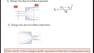
Now let us go to the minor losses in the pipe systems. As I told it when you have the pipes, it can have a regions you have a smaller pipe to bigger pipe or bigger pipe to the smaller pipe. When you have a these conditions that means the flow is coming it here and going out, the smaller diameters and the larger diameter. If you have these conditions, what we do it that when you compute the energy losses, for this total regions, we compute the analysis this.
Detailed Explanation
In pipe systems, when fluid flows from a larger to a smaller diameter or vice versa, energy losses can occur. These losses are influenced by various factors, including the pipe's geometry and flow characteristics. Energy losses are calculated across these transitions to assess the efficiency of the fluid movement.
Examples & Analogies
Think of a water slide in a water park. If the slide is wide at the beginning and then narrows down, the water rushes faster through the narrow part. However, if the transition is abrupt, some energy is lost due to turbulence and friction, just like in fluid dynamics.
Understanding Major vs. Minor Losses
Chapter 2 of 5
🔒 Unlock Audio Chapter
Sign up and enroll to access the full audio experience
Chapter Content
So we can quantify it or you conduct the experiments. It is very easy to conduct the experiment of different pipe diameters, different configurations you can compute it. You just measure the pressure at these two points and you know the velocities like the manometers you can put it then you can measure the pressure difference and you can easily quantify that how much of K value from experimentally.
Detailed Explanation
In terms of fluid mechanics, there are two main types of losses: major losses, which are primarily due to friction in the pipes, and minor losses, which are due to fittings, bends, valves, and other disturbances in the flow. Conducting experiments with different pipe setups allows us to measure these losses accurately, particularly by measuring pressure differences at set points using manometers.
Examples & Analogies
Imagine a garden hose with a nozzle at the end. When you cover half of the nozzle’s opening with your finger, you create a restriction that increases pressure in the hose but also leads to a loss of flow speed. Here, the friction from the hose and the restriction at the nozzle represent major and minor losses, respectively.
Flow Characteristics and Energy Losses
Chapter 3 of 5
🔒 Unlock Audio Chapter
Sign up and enroll to access the full audio experience
Chapter Content
Now let us look it how would it happens it. That again I am considering virtual fluid balls okay. If I consider the virtual fluid balls, the balls which is going very close to the wall, which will go straight and inject here as a tangential and go like this, okay. What will happen to this? Here also we have the particular liquid, but that liquid will have a vortex formation. They will start rotating it, start rotating it. So immediately your flow will pass this, these regions will have a vortex formations.
Detailed Explanation
When fluid flows close to the pipe wall, it can create vortex formations due to changes in flow direction or velocity. These vortices contribute to energy losses because they disrupt the smooth flow of the fluid, which can lead to increased turbulence and friction.
Examples & Analogies
Consider stirring a cup of coffee. As you stir, the coffee develops whirlpools. These disturbances create a chaotic flow, analogous to how vortices in fluid systems create additional friction and energy loss, making it harder for the fluid to flow smoothly.
Impact of Bends and Turns on Flow
Chapter 4 of 5
🔒 Unlock Audio Chapter
Sign up and enroll to access the full audio experience
Chapter Content
Now if you look it that the because of this mixing layers, because of the vortex formations, and the presence of the vortex formations you can feel it if you are engineers just touch these pipes, you can see this heat is generating it. You can see the temperature difference. So that means, indirectly it indicates for us there is a vortex formations are happening it.
Detailed Explanation
Bends in piping systems can cause additional energy losses due to the creation of vortices. These vortices result in turbulence, which not only hinders flow but can also generate heat due to friction. Understanding these phenomena helps engineers design more efficient piping systems by minimizing sharp turns.
Examples & Analogies
Think of driving a car around a sharp curve. As you turn, you feel the forces pushing you outside the turn. Similarly, in pipes, bends can push the fluid in unwanted directions, creating vortices that cause energy loss and potentially even overheating in the system.
Contraction and Expansion Flow Effects
Chapter 5 of 5
🔒 Unlock Audio Chapter
Sign up and enroll to access the full audio experience
Chapter Content
But interestingly let us go for that is two systems okay, which I intentionally putting to you that just look at these figures. One is expansions another is contractions. The flow is comes from this side and goes like this side. In this case also flow goes like this. Now if you look at the steamlines, which is just closer to the wall, in this case, it happens like this.
Detailed Explanation
When fluid flows through sections of varying diameter—either contracting (narrowing) or expanding (widening)—energy losses differ. Contracting flows tend to create more significant vortex formations, leading to higher energy losses compared to expanding flows, where these formations are minimized.
Examples & Analogies
Consider a funnel. When pouring water into a narrow neck (contraction), water tends to splash and create turbulence. However, as the funnel opens up, the water flows smoothly out, demonstrating how expansions can help reduce turbulence and energy loss.
Key Concepts
-
Major Losses: Energy losses due to friction in pipes, described by the Darcy-Weisbach equation.
-
Minor Losses: Losses due to fittings or changes in flow direction/area, calculated using K-values.
-
Friction Factor: A crucial parameter for calculating major losses.
-
Reynolds Number: Important for distinguishing flow types.
-
K-value: Utilized for quantifying minor losses in pipe fittings.
Examples & Applications
Example of calculating major losses using given flow conditions and the Darcy-Weisbach equation.
Example of determining minor losses from a pipe fitting using provided K-values.
Memory Aids
Interactive tools to help you remember key concepts
Rhymes
Major losses due to friction, minor ones from pipe fittings; remember, smooth flow brings the best sittings.
Stories
Imagine a river navigating through a city. The friction from the riverbanks is a major loss, while the bridges and pipes it encounters are minor losses affecting its journey.
Memory Tools
Remember 'FIR' for losses: F for Friction (Major), I for Installations (Minor), and R for Reynolds number.
Acronyms
F.M.P - Friction (Major Losses), Minor Losses, Pressure Drop.
Flash Cards
Glossary
- Major Losses
Energy losses predominantly due to friction in pipes, quantified by the Darcy-Weisbach equation.
- Minor Losses
Energy losses that occur due to fittings and changes in flow conditions within pipe systems.
- Friction Factor
A dimensionless number that represents the resistance to flow due to friction in a pipe.
- Reynolds Number
A dimensionless quantity used to indicate whether flow is laminar or turbulent.
- Kvalue
A coefficient representing minor loss due to pipe fittings and changes in flow direction or diameter.
Reference links
Supplementary resources to enhance your learning experience.